background image

Handheld Configuration Devices

Model DHH805-A

Operating Instruction OI/DHH805-EN Rev. D

DHH805-A Configuration Device 

with HART

®

 Communications

Summary of Contents for DHH805-A

Page 1: ...Handheld Configuration Devices Model DHH805 A Operating Instruction OI DHH805 EN Rev D DHH805 A Configuration Device with HART Communications ...

Page 2: ...ns As a part of ABB a world leader in process automation technology we offer customers application expertise service and support worldwide We are committed to teamwork high quality manufacturing advanced technology and unrivalled service and support The quality accuracy and performance of the Company s products result from over 100 years experience combined with a continuous program of innovative ...

Page 3: ...er dongle 15 6 3 Navigating menus on the DHH805 A display 15 6 4 Turning the DHH805 A on 15 6 5 DHH805 A settings 16 6 5 1 Settings 16 6 5 2 Communication 16 6 6 NiMh Battery Considerations 16 7 HART communications 17 7 1 Overview 17 7 2 HART Commands 17 7 3 HART Connections 17 7 4 Generic HART Commands 18 7 5 HART Communication Online Mode 19 7 6 Multidrop Poll addresses 1 63 19 7 7 Offline menu ...

Page 4: ...a smart interface with HART electronic devices it is designed to enable the plant engineer to configure calibrate and troubleshoot the transmitters either before or after field installation The Hand Held Communicator can store in its non volatile memory hundreds of transmitter configurations The Communicator employs a four line by twenty dot matrix characters LCD and a 23 key tactile feedback keyb...

Page 5: ...ing situation Warning Bodily injury This message indicates a potentially dangerous situation Failure to avoid this could result in death or serious injury Attention Property damage This message indicates a potentially damaging situation Failure to avoid this could result in damage to the product or its surrounding area 2 3 Qualified personnel Operations on the device may only be performed by train...

Page 6: ...on the order acknowledgment by the supplier 2 9 Safety information for electrical installation Warning Electrical connections may only be established by authorized specialist personnel in accordance with the electrical circuit diagrams The electrical connection information in the manual must be observed otherwise the applicable protection type may be affected 2 10 Contacting ABB Should assistance ...

Page 7: ...figured polled and trimmed using the DHH805 A with HART communications Figure 1 DHH805 A overview 1 Important For Intrinsically Safe applications refer to the Hazardous Area Use section of this manual For specific details on use of approved DHH805 A and applicable restrictions refer to Intrinsic Safety Control Drawings in Section 9 of this manual 1 HART connectors 2 Protective plastic cover 3 USB ...

Page 8: ...usting Display Contrast wait at least five 5 seconds before turning unit off to insure storage of new contrast setting BACKLIGHT This key toggles the backlight feature between Very low intensity Low intensity Mid intensity High intensity to illuminate the display in poor ambient light conditions Battery life is affected by use of the backlight feature High intensity is the most aggressive To disab...

Page 9: ...Hz or AMD Athlon 64 X2 4400 processor Screen resolution of 1024x768 or greater Broadband Internet connection DVD ROM reader Software Latest Windows XP Windows 7 or Windows Vista Service Packs 1 gigabyte GB RAM 32 bit for XP version or 1 5 gigabyte GB RAM 32 bit for Windows 7 and Windows Vista 200 megabytes MB to 2 gigabytes GB available hard disk space 32 bit Microsoft NET Framework 3 5 or later 2...

Page 10: ...d the DHH805 tag Note DHH805 tag can be found printed on the white cardboard packing box or on the DHH805 screen under Activation Manually DHH805 tag After you receive the activation code enter it by the following Activation Manually Activation Code Edit Device activated succesfully will appear when it is complete Note To perform the activation Via PC Tool an internet connection may be required To...

Page 11: ...al or a single entity and ABB SpA ABB for the ABB Software accompanying this EULA which includes computer software and may include associated media printed materials and online or electronic documentation SOFTWARE PRODUCT or SOFTWARE By installing copy or otherwise using the SOFTWARE PRODUCT you agree to be bound by the terms of this EULA If you do not agree to the terms of this EULA discontinue i...

Page 12: ...ied concerning such matters and notwithstanding any provisions to the contrary shall take precedence over any conflicting terms which may be contained in your purchase order acknowledgement form This EULA states the entire obligations of ABB in connection with the SOFTWARE PRODUCT PROGRAM REMAINS ABB S PROPERTY All rights not specifically granted under this EULA are reserved by ABB All title and i...

Page 13: ...nybody outside ABB without your previous written authorization YES I authorize ABB to collect and handle my data NO I do not authorize ABB to collect and use my personal data 4 5 3 ABB S p A Data Acquisition and Handling Authorization IMPORTANT READ CAREFULLY In the philosophy of continuous product improvement ABB SpA may collect data related to the functionality of your DHH805 A as well as the on...

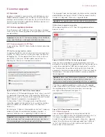
Page 14: ...ree dedicated telephone numbers a specialist will help users in upgrading DHH805 A license Important License upgrade is subject to Purchase Order to ABB When performing the off line procedure please always mention our Order Acknowledgment number and device DHH805 tag The Upgrade Code once received should be written inside the dedicated box see figure 9 of the PC Tool or keyed in on the DHH805 A Up...

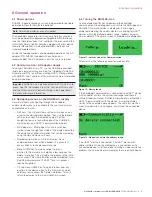
Page 15: ...ll bar symbol along the right hand side of the display indicating the existence of other information that can be viewed by using the Up and Down soft keys Numbered item menus All items displays have numbered menu lines when needed This gives fast access directly to the desired menu line Menu HOME key To quickly retreat from any location to the main menu hold for a few seconds the Delete Help key T...

Page 16: ...Revision this submenu contains information about software hardware and FPGA revision Memory info by navigating through this submenu user will have a clear idea of memory status Memory info shows the number of uploaded DDs and configurations total and used memory as well as free space on SD card Language DHH805 A features a multi language menu By editing this setting users can choose between Englis...

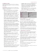
Page 17: ...T field devices First Universal Commands are primarily used to identify a field device by its model number and tag number and to read process data from the device This communication is referred to as polling The DHH805 A can poll any HART Device Second Common Practice Commands are used for calibration and maintenance functions that are common to many devices An example of this would be trims or ad...

Page 18: ...ER command 34 WRITE PV DAMPING VALUE command 7 READ LOOP CONFIGURATION command 7 READ LOOP CONFIGURATION command 35 WRITE PRIMARY VARIABLE RANGE VALUES command 8 READ DYNAMIC VARIABLE CLASSIFICATIONS command 8 READ DYNAMIC VARIABLE CLASSIFICATIONS command 36 SET PRIMARY VARIABLE UPPER RANGE VALUE command 20 READ LONG TAG command 20 READ LONG TAG command 37 SET PRIMARY VARIABLE LOWER RANGE VALUE co...

Page 19: ... address 0 addresses from 1 to 15 HART 5 addresses from 1 to 63 HART 6 and HART 7 or a customized range as shown in figure 16 As mentioned in paragraph 6 5 1 default polling address is 0 Figure 16 No device within the address range After selecting the desired address range to be polled DHH805 A shows the list of all devices within that range sorted by tag see figure 17 7 7 Offline menu mode After ...

Page 20: ...5 Editable configuration parameters in offline mode This list features the Info icon By pushing the Delete Help button user can read some detailed information about all editable parameters of the selected configuration see figure 25 Parameter editing is extremely simple By selecting the Edit push button user can modify and customize all configuration entries Figure 26 Information on editable confi...

Page 21: ...rly User can find further details under DD diagnostics MSA More Status Available DD diagnostics is to be checked PRO Process handheld terminal shows this status message when device variables process and non process are out of limits as well as when the loop current is saturated More details can be found under DD diagnostics 7 10 Save send configuration functions HART device configurations may be s...

Page 22: ...pan OPERATIONAL LIMITS Max Temperature Limit Min Temperature Limit Max Working Pressure UNIT Temperature Unit UNIT Temperature Unit Static Pressure Unit SENSOR MATERIALS BASIC SENSOR MATERIALS Diaphragm Material Filling Fluid GAUGE SENSOR Process Connection Material PROCESS CONNECTION HIGH SIDE Connection Type Flange Material O Ring Material Blanking Plug PROCESS CONNECTION LOW SIDE Connection Typ...

Page 23: ...Unit DISPLAY GENERAL Display Revision GENERAL Display Revision Contrast Language DISPLAY SETTING Display Mode Line 1 View Line 2 View Bargraph View DISPLAY SCALING Linearization Type Unit Custom Unit Upper Range Value Lower Range Value CALIBRATION PRESSURE SENSOR Cal Pressure Full trim Zero trim Integration Time Sensor Temperature Sensor Temperature Trimming STATIC PRESSURE Cal Static Pres Full tr...

Page 24: ...Diagnosis Simulation Group1 Diagnosis Simulation Group1 CONFIGURATION ELECTRONICS Diagnosis Masking Byte 2 Diagnosis Masking Byte 3 INSTALLATION START UP Diagnosis Masking Byte 4 OPERATING CONDITIONS Diagnosis Masking Byte 4 Diagnosis Masking Byte 5 SENSOR ACTUATORS Diagnosis Masking Byte 2 PROCESS Diagnosis Masking Byte 4 Diagnosis Masking Byte 0 Diagnosis Masking Byte 0 Diagnosis Masking Byte 0 ...

Page 25: ...r Uppper Limit Sensor Lower Limit Sensor Min Span Sensor probe type Sensor CJC type Sensor CJC temperature Sensor Uppper Limit Sensor Lower Limit Sensor Min Span CURRENT OUTPUT PV Unit Range 4mA To 20mA Damping Reaction on errors Underrange value Overrange value SIMULATE Loop test CALIBRATE SENSOR TRIM One point trim Reset trim CURRENT OUTPUT TRIM D A trim EXTRA Reset to factory OBSERVE OBSERVE PV...

Page 26: ...s Linearity status Signal noise ratio status MODE Mass short circuit coil status Electrodes state status Start Diagnosis Start Diagnosis manual EXT DIAG HISTORY COIL CURRENT Wrk hrs Converter Wrk hrs Converter 1 Wrk hrs Converter 2 Wrk hrs Converter 3 Wrk hrs Converter 4 Wrk hrs Converter 5 Wrk hrs Converter 6 Wrk hrs Converter 7 Wrk hrs Converter 8 Wrk hrs Converter 9 Wrk hrs Primary Wrk hrs Prim...

Page 27: ...rature 4 Coil temperature 5 Coil temperature 6 Coil temperature 7 Coil temperature 8 Coil temperature 9 Coil temperature min Coil temperature max Set to default COIL ISOLATION RESISTANCE Wrk hrs Converter Wrk hrs Converter 1 Wrk hrs Converter 2 Wrk hrs Converter 3 Wrk hrs Converter 4 Wrk hrs Converter 5 Wrk hrs Converter 6 Wrk hrs Converter 7 Wrk hrs Converter 8 Wrk hrs Converter 9 Wrk hrs Primary...

Page 28: ... E2 2 Electrode voltage E2 3 Electrode voltage E2 4 Electrode voltage E2 5 Electrode voltage E2 6 Electrode voltage E2 7 Electrode voltage E2 8 Electrode voltage E2 9 Electrode voltage E2 min Electrode voltage E2 max Set to default ELECTRODE BALANCE Wrk hrs Converter Wrk hrs Converter 1 Wrk hrs Converter 2 Wrk hrs Converter 3 Wrk hrs Converter 4 Wrk hrs Converter 5 Wrk hrs Converter 6 Wrk hrs Conv...

Page 29: ...DAC Electrode voltage E1 Electrode voltage E2 Electrode balance Linearity Signal noise ratio Wrk hrs Converter P1 Wrk hrs Primary P1 PRODUCT 1 Coil current P1 Coil voltage P1 Coil resistance P1 Coil temperature P1 Coil isolation resistance P1 DAC P1 Electrode voltage E1 P1 Electrode voltage E2 P1 Electrode balance P1 Linearity P1 Signal noise ratio P1 Copy current to p1 Wrk hrs Converter P2 Wrk hr...

Page 30: ... adj Sys zero PS Code DISPLAY MODE Display mode 1st line 2nd line 3rd line 4th line Language ALARMS Max Alarm Min Alarm Iout at Alarm Iout Low Alarm Iout High Alarm Alarm e pipe Iout at e pipe Contact output Error 3 mask Error 4 mask PRIMARY Span Adjust Zero Adjust Phase Referencevoltage Order Number Calib Date Tester Testrig Cal fact 10m s Frequency Primary Type of Primary Metersize CONVERTER Spa...

Page 31: ...int range max Setpoint damping ramp down Setpoint damping ramp up Setpoint filter Setpoint Configuration DIGITAL INPUT Digital input function Digital input logic DI default setpoint Digital Input Configuration UNIVERSAL INPUT SCALING True current Input INPUT RANGE Min Max Set input range DAMPING Damping ramp Set damping ramp CHARACTERISTIC CURVE Input characteristic Set input characteristic USER C...

Page 32: ...Value Min travel value Set Maintenance counters limit VALVE PARAMETER END POSITION BEHAVIOUR 0 Tight shut End Position 0 Dead angle End Position 0 Control at 0 Config End Position 0 END POSITION BEHAVIOUR 100 Tight shut End Position 100 Dead angle End Position 100 Control at 100 Config End Position 100 DEVICE SET UP BASIC SETTING Vent position Actuator type Setpoint direction Setpoint characterist...

Page 33: ...rrent status Pressure Y1 Pressure Y1 status Pressure Y2 Pressure Y2 status Differential pressure Differential pressure status Supply pressure Temperature Travel counter Movement counter True current Input Calculated value Output TREND VALUES CHART VALUES PRESSURE VALUES OTHERS BAR GRAPHS BAR GRAPH PROCESSES BAR GRAPH PRESSURE BAR GRAPH OTHERS ADJUST SET VALUES ADJUST SET VALUES RANGES Valve lower ...

Page 34: ...V Down Ref Set TV Down Ref ZERO POINT DISPLACMENT Zero Point Deviation Value Set Zero Point Deviation GENERAL SETTINGS Time latch Set Time Latch NE107 CONFIGURATION SENSOR Position measurement Failure Edit OPERATION OPERATION 1 Setpoint out of range Edit Controller inactive Edit Electronic temperature out of limits Edit Overpressure from supply Edit Supply pressure limit low exceeded Edit Supply p...

Page 35: ...EEDBACK Check function Edit Off specification Edit Maintenance Edit Failure Edit DIGITAL FEEDBACK Switch 1 Edit Switch 2 Edit DRAG INDICATORS Config time window CONTROL DEVIATION ENDLESS Min Average Max Reset DAYS Min Average Max Reset HOURS Min Average Max Reset TEMPERATURE ENDLESS Min Average Max Reset DAYS Min Average Max Reset HOURS Min Average Max Reset SUPPLY PRESSURE ENDLESS Min Average Max...

Page 36: ...OURS 0 HRS 0 10 HRS 10 20 HRS 20 30 HRS 30 40 HRS 40 50 HRS 50 60 HRS 60 70 HRS 70 80 HRS 80 90 HRS 90 100 HRS 100 HRS Reset hours TREND MAIN USED VALVE POSITION ENDLESS 0 EL 0 10 EL 10 20 EL 20 30 EL 30 40 EL 40 50 EL 50 60 EL 60 70 EL 70 80 EL 80 90 EL 90 100 EL 100 EL Reset endless DAYS 0 DAYS 0 10 DAYS 10 20 DAYS 20 30 DAYS 30 40 DAYS 40 50 DAYS 50 60 DAYS 60 70 DAYS 70 80 DAYS 80 90 DAYS 90 1...

Page 37: ...RICTION ENDLESS 0 EL 0 10 EL 10 20 EL 20 30 EL 30 40 EL 40 50 EL 50 60 EL 60 70 EL 70 80 EL 80 90 EL 90 100 EL 100 EL Reset endless DAYS 0 DAYS 0 10 DAYS 10 20 DAYS 20 30 DAYS 30 40 DAYS 40 50 DAYS 50 60 DAYS 60 70 DAYS 70 80 DAYS 80 90 DAYS 90 100 DAYS 100 DAYS Reset days HOURS 0 HRS 0 10 HRS 10 20 HRS 20 30 HRS 30 40 HRS 40 50 HRS 50 60 HRS 60 70 HRS 70 80 HRS 80 90 HRS 90 100 HRS 100 HRS Reset ...

Page 38: ...ounter Total travel counter limit Set Limit MOVEMENT COUNTERS Movement counter Movement counter limit Set Limit POWER DOWN CYCLES Power down counter DATA PRODUCTION DATE Production date Production time VALVE MOUNTING DATE Valve mounting date Valve mounting time Set valve mounting date HOST DATE Host date Host time Set Host Time Total time since production Total time since valve mounted Total opera...

Page 39: ... Test status met Start test met Stop test GRAPH met Get trend met Save to archive met Load from archive STEP RESPONSE TEST SETTINGS Start position Stop position Interval met Set parameters TEST Diagnosis mode Progress Test status met Start test met Stop test GRAPH met Get trend met Save to archive met Load from archive Important DD structure changes according to instrument design Repeated entries ...

Page 40: ...Note When internet resources and DHH805 A connection are not in place the icons are coloured grey License type and DHH805 tag icon is active only when the device is connected Update icon blinks when new software and or firmware release s is are available Figure 32 PC Tool DD manager 1 PC Tool tree 2 Transfer button 3 Upload DDs to PC 4 Recycle bin of left tree 5 DHH805 A tree 6 Upload button 7 Rec...

Page 41: ...A blinking icon in the lower right hand corner and a warning message will inform the user of new software and or firmware releases Select the manual update option to update firmware manually if there is no internet service available or required firmware update forcefully 8 4 3 Help Under the Help menu user can find details about PC Tool Help the three submenus gives users suggestions and informati...

Page 42: ...te the selected item Delete checked Delete the checked items under the selected item Figure 36 Action drop down box Check Select any item and check The selected item and all of its sub items will be checked Uncheck Select any item and uncheck The selected item and all of its sub items will be unchecked Copy to right Select any item and Copy to right The selected item and all of its sub items will ...

Page 43: ...ted automatically G017 Try again later S001 Close PC Tool and shut down DHH805 A S002 Close PC Tool and shut down DHH805 A S003 Error removing generic DD Close PC Tool and shut down DHH805 A S004 Error writing generic DD Close PC Tool Shut down DHH805 A If the problem persists please extract SD card and format it S005 Error writing new generic DD Close PC Tool and shut down DHH805 A S006 Close PC ...

Page 44: ...e Intel Core 2 Duo 2 4 GHz or o AMD Athlon 64 X2 5600 2 8 GHz processor Broadband Internet connection 1 DVD ROM reader Software Latest Windows 7 Service Pack 4 gigabyte GB RAM 32 bit 3 gigabytes GB available hard disk space 32 bit 2 Note 1 Some wireless connections can not be defined as broadband internet connections Results with wireless connections may vary 2 Worse case by importing the entire D...

Page 45: ...onents may impair Intrinsic Safety To prevent ignition of flammable or explosive atmospheres Disconnect power before servicing DO NOT open the unit including battery compartment or attempt to service the unit when located in flammable or potentially explosive atmosphere Remove to safe area DO NOT use the general purpose AA battery pack in hazardous areas DO NOT use the elastic band in hazardous ar...

Page 46: ...215 mA P max 0 85 W Ci 0 04 uF Li 0 mH Voc 2 6 Vdc Isc 18 mA Po 61mW Ca 99 uF La 100mH Note For FMc Approval use the FMc barriers according to Canadian Zone Concept 30 V max 330 ohms min 28 V max 300 ohms min 22 V max 180 ohms min Intrinsically safe FM c CL 1 Zone 0 IIC T4 Warning Use of the charger port is not allowed while the DHH805 A is connected or located in hazardous area Warning Use of the...

Page 47: ...te see paragraph 9 2 3 for Non Incendive Component Field Wiring Non Incendive Parameters V max 42 Vdc I max 250 mA Ci 0 04 uF Li 0 mH Voc 2 6 Vdc Isc 47 mA Ca 99 uF La 100mH Non Incendive Warning Use of the charger port is not allowed while the DHH805 A is connected or located in hazardous area Warning Use of the USB port is not allowed while the DHH805 A is connected or located in hazardous area ...

Page 48: ...Vt Isc or It Ca and La for barriers are provided by the barrier manufacturer Non incendive Component Field Wiring concepts The Non Incendive field wiring concept is very similar to the entity concept except it allows devices approved with Non Incendive Component Field Wiring parameters to be installed in Division 2 hazardous classified location when connected to the appropriate sources of power pr...

Page 49: ... DANGEROUS FLUIDS In case of toxic or otherwise dangerous fluid please attach the relevant Material Safety Data Sheet Trouble found during Installation Commissioning Maintenance At start up On service Shipping information for the return of the equipment Material returned for factory repair should be sent to the nearest ABB Service Center transportation charges prepaid by the Purchaser Please enclo...

Page 50: ...and dismantle without any special precautions Material s which have been in contact with this equipment C If A or B are not applicable full instructions for the safe handling of this equipment for disposal must be supplied Please delete A B or C above as applicable complete the signature section below then send the completed declaration either with the returned items or by fax for the attention of...

Page 51: ...Handheld communicator Model DHH805 A OI DHH805 EN Rev D 51 ...

Page 52: ...52 OI DHH805 EN Rev D Handheld communicator Model DHH805 A ...

Page 53: ...Handheld communicator Model DHH805 A OI DHH805 EN Rev D 53 Intentionally blank ...

Page 54: ...54 OI DHH805 EN Rev D Handheld communicator Model DHH805 A Intentionally blank ...

Page 55: ... certified level transmitters ABB s portfolio of device management Fieldbus and wireless solutions Scalable asset device management Asset vision software Mobility handhelds Customer support We provide a comprehensive after sales service via a Worldwide Service Organization Contact one of the following offices for details on your nearest Service and Repair Centre ABB S p A Via Statale 113 22016 Len...

Page 56: ...1 Fax 39 0344 56278 www abb com Contact us Note We reserve the right to make technical changes or modify the contents of this document without prior notice With regard to purchase orders the agreed particulars shall prevail ABB does not accept any responsibility whatsoever for potential errors or possible lack of information in this document We reserve all rights in this document and in the subjec...

Reviews: