


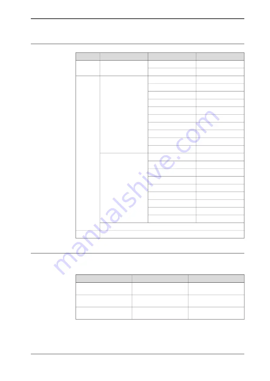
Connectors
Right side/description
Left side/description
Connector
Location
4 - PWR
2 - PWR
X4 Logic power
Top
3 - GND
1 - GND
20 - PWR DO
10 - PWR DO
X1 Digital outputs, pro-
cess power
i
Front
19 - GND DO
9 - GND DO
18 - DO09
8 - DO01
17 - DO10
7 - DO02
16 - DO11
6 - DO03
15 - DO12
5 - DO04
14 - DO13
4 - DO05
13 - DO14
3 - DO06
12 - DO15
2 - DO07
11 - DO16
1 - DO08
18 - GND DI
9 - GND DI
X2 Digital inputs
17 - DI09
8 - DI01
16 - DI10
7 - DI02
15 - DI11
6 - DI03
14 - DI12
5 - DI04
13 - DI13
4 - DI05
12 - DI14
3 - DI06
11 - DI15
2 - DI07
10 - DI16
1 - DI08
X3 EtherNet
X5 EtherNet
Down
i
The numbers (printings) on the module only show the I/O numbers (digital input/output). It is not
the pin position number for connector X1 or X2 (only I/O number).
Reset button
The DSQC1030 base device has a reset button located under the status LEDs. The
reset button can be used in different ways to reset the device.
Indication
Description
Function
Regular reset, same as tog-
gling the power.
Pressed once (<3 sec)
The Power LED flashes red
once.
Resets the IP-settings to ABB
default values.
Short press and hold (>3 sec)
The Power LED flashes red
two times.
Factory reset.
Long press and hold (>10
sec)
Continues on next page
Application manual - Discrete I/O
27
3HAC070208-001 Revision: C
© Copyright 20192020 ABB. All rights reserved.
2 Hardware overview
2.3.1 DSQC1030 Digital base
Continued
Summary of Contents for Discrete I/O
Page 1: ...ROBOTICS Application manual Discrete I O ...
Page 6: ...This page is intentionally left blank ...
Page 14: ...This page is intentionally left blank ...
Page 56: ......
Page 57: ......


