


6
Table 3 - Mounting Motors to C-Faced Reducers
For Clamp Collar Input Reducers
(Reference Figure 4 & 5)
Prepare the motor by checking the motor shaft extension for
dirt or damage. Use solvent to remove all traces of anti-rust
coating that may be on the shaft.
Check the input bore for dirt or damage. Clean the bore with
solvent to remove all traces of oil or anti-rust coating.
For NEMA motors ONLY: A special long, tall motor key is
provided with the Quantis unit.
1. Discard the motor key and replace it with the special key
provided. DO NOT USE THE MOTOR KEY.
2. If the special key does not fit snugly in the motor shaft
keyway, prepare the key for assembly by nicking its
bottom in a couple of spots. A chisel may be used to
accomplish this. This must be done on a work surface
away from the Quantis unit and the motor. This nicking
should widen the key bottom and cause it to fit snugly in
the motor keyway. Refer to Figure 5 for definition of key
bottom.
3. Install the key in the motor shaft keyway by lightly
tapping it in place with a rubber mallet.
4. Locate the key so that it sits flat in the motor shaft
keyway. The key will probably extend beyond the end of
the motor shaft. This is OK. The key MUST NOT sit tilted
in the keyway. A tilted key can occur when a motor shaft
has a sled runner keyway, Refer to Figure 5.
5. Mark the clamp collar with a fine tipped marker on both
sides of the setscrew to indicate where the center of the
set screw is located. Run a line down both sides of the
clamp collar that line up with the line previously created.
6. Remove the socket head screw and set screw from
the clamp collar and apply Loctite 243 thread locker.
Reinstall the screws into the clamp collar. Install the
clamp collar onto the reducer input shaft and line up the
mark previously made on the clamp collar with the center
of the keyway in the shaft. If the clamp collar rotates
freely, tighten the clamping screw slightly to keep it from
rotating during assembly. Make sure the marked line is
pointing to the center of the keyway.
The Dodge Quantis RHB C-Face reducer should be firmly
anchored to prevent sliding as the motor is mounted. The
motor should be rotated on its axis so the motor flange holes
line up with the C-Face adapter holes. Check to be sure the
motor conduit box, grease fittings and condensate drains
(where fitted) will be oriented as needed by the reducer
mounting position.
Hoist motor level and in line with reducer input shaft. For EZ
Kleen Quantis reducers with 180TC or larger NEMA input,
install the o-ring provided onto the motor pilot to seal the
input assembly from water ingress.
Align the motor shaft with the gear reducer input bore making
sure that the motor shaft keyway is in line with the input bore
key. Push the motor into place. Motor shaft to input bore
clearances are tight and good alignment is essential.
Insert and tighten the motor retaining bolts. Tighten to the
correct torque value listed below.
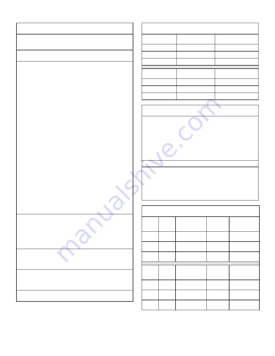
Table 3 - Mounting Motors to C-Faced Reducers
For Clamp Collar Input Reducers
(Reference Figure 4 & 5)
NEMA Motor
Frame
Motor Bolt
Bolt Tightening
Torque
56C, 140TC
3/8-16
236 lb-in (27 Nm)
180TC,
1/2-13
516 lb-in (58 Nm)
IEC Motor
Frame
Motor Bolt
Bolt Tightening
Torque
71
M8
188 lb-in (21 Nm)
80, 90
M10
372 lb-in (42 Nm)
100
M12
648 lb-in (73 Nm)
FOR CLAMP COLLAR INPUT REDUCERS
(Reference Figure 4)
View the clamp collar through the access holes in the C-face
adapter.
1. Rotate the clamp collar to locate the setscrew over the
key, if necessary.
2. Tighten the setscrew to the torque referenced below.
3. Reach through the access hole in the C-face adapter
with a hex socket and tighten the clamp collar clamping
bolt to the torque value given below.
Replace the access hole plugs in the C-face adapter.
NOTE: A TEE handle hex key wrench is not stiff enough
to properly tighten the clamp collar bolt. A socket
wrench extension with a hex insert must be used in
conjunction with a torque wrench. Failure to tighten
the clamp collar to the proper torque may result in
movement between motor and reducer shafts and cause
premature wear on the shafts and keys.
FOR CLAMP COLLAR INPUT REDUCERS
(Reference Figure 2)
NEMA
Motor
Frame
Clamp
Bolt
Clamp Bolt
Tightening
Torque
Setscrew
Size
Set Screw
Tightening
Torque
56
M6
132 lb-in
(15 Nm)
M4
27 lb-in
(3 Nm)
140
M6
132 lb-in
(15 Nm)
M4
27 lb-in (
3 Nm)
180
M8
312 lb-in
(35 Nm)
M6
90 lb-in
(10 Nm)
IEC
Motor
Frame
Clamp
Bolt
Clamp Bolt
Tightening
Torque
Setscrew
Size
Set Screw
Tightening
Torque
80
M6
132 lb-in
(15 Nm)
M4
27 lb-in
(3 Nm)
90
M8
312 lb-in
(35 Nm)
M6
90 lb-in
(10 Nm)
100
M8
312 lb-in
(35 Nm)
M6
90 lb-in
(10 Nm)


