—
ABB Motors and Mechanical Inc.
5711 R. S. Boreham Jr. Street
Fort Smith, AR 72901
Ph: 1.479.646.4711
Mechanical Power Transmission Support
Ph: 1.864.297.4800
new.abb.com/mechanical-power-transmission
baldor.com
All Rights Reserved. Printed in USA.
10/19
© ABB Motors and Mechanical Inc.
MN16022
*16022-1019*
VB
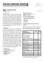
RETAINING BOLT M
ROUND KEYED NUT
UY
Y
x
UE
FG
x
FH
FV
M1-TAP
REMOVAL BOLT
M1
VB1
S
DISK
x
UE
GF
MACHINE'S
DRIVE SHAFT
VL
x
UG
M-TAP
2.5 x M
MINIMUM
CUSTOMER SUPPLIED KEY.
REFERENCE GEARCASE DIMENSIONS
FOR RECOMMENDED KEY.
x
RS
Straight Hollow Bore Assembly / Disassembly
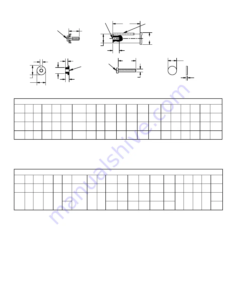
Table 5 - INCH SHAFTS for Straight Hollow Bore Installation Dimensions - Inch
Unit
Size
FG
Ø
FH
FV
GF
M
M1
M4
S
Ø U
Y Max.
Ø
UE
Ø
UG
tol.
UY Max
VL
VB
VB1
VG
Ø RS
②
B_38
0.38 0.75 0.625
0.12
3/8-16
3/8-16
1.73
0.31
1.250
0.250
1.245
1.250
+0.000
-0.0006 1.367
3.50
1.75
6.00
4.02
1.75
B_48
0.38 0.93 0.625
0.12
3/8-16
5/8-18
2.28
0.50
1.375
0.312
1.370
1.375
+0.000
-0.0006
1.52
4.50
1.75
7.00
5.04
1.875
B_48
0.38 0.75 0.625
0.12
3/8-16
5/8-16
1.73
0.31
1.250
0.250
1.245
1.250
+0.000
-0.0006 1.367
4.50
1.75
7.00
5.04
1.75
Hollow shaft tolerances (For dimension U) are shown in the gearbox dimension pages.
Tolerance for dimension UE should be -0.01 in for inch bore shafts
Bold shaft diameters indicate standard shaft
②
RS Dimension is the minimum recommended shaft shoulder diameter
Straight Hollow Bore Assembly / Disassembly
Table 6 - METRIC SHAFTS for Straight Hollow Bore Installation Dimensions - millimeters
Unit
Size
FG
Ø FH
FV
GF
M
M1
M4
S
Ø U
Y Max.
Ø UE
Ø UG
tol.
UY Max
VL
VB
VB1
VG
Ø RS
②
B_38
10
9
15
6
M10
M10 x 1.5
44
8
30
8
29.9
30
+0.000
-0.013
33
90
40
150
102
42
B_48
9
22
15
6
M12
M12 x 1.5
58
10
35
10
34.9
35
+0.0000
-0.0016
38
115
60
180
128
47
M16
40
12
39.9
40
+0.0000
-0.0016
43
52
Hollow shaft tolerances (For dimension U) are shown in the gearbox dimension pages.
Tolerance for dimension UE should be -0.02 mm for metric bore shafts.
Bold shaft diameters indicate standard shaft
②
RS Dimension is the minimum recommended shaft shoulder diameter