background image

13

R

e

p

lac

e

m

e

n

t P

a

rt

s f

o

r U

S

N 2

0

0 D

ir

e

c

t M

o

u

n

t P

lu

m

m

e

r B

loc

ks

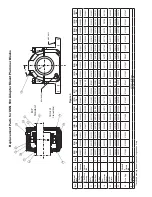
DR

AIN HOLE 

BOL

T HOLE

30

˚

 NON-EXP Closed End

26

26

     EXP Standar

d

16

16

25

31

24

F

ig

u

re 5

Re

f. 

Na

m

e o

Par

St

yl

Qt

y.


(2

09) 45 

(2

10

)

50 

(2

11

)

55 

(2

12

)

60 

(2

13

)

65 

(2

15

)

75 

(2

16

)

80 

(2

17

)

85 

(2

18

)

90 

(2

19

)

95 

(2

20) 10

(222

)

11

(2

24) 12

(2

26) 13

(2

28) 14

(2

30) 15

(2

32

)

16

12


2-

Bo

lt B

as

Ho

us

in

St

an

da

rd


03

99

46 

03

99

48 

03

99

50 

03

99

52 

03

99

54


03

99

56 

03

99

58 

03

99

60 

03

99

62 

03

59

41


03

9964


03

99

66


03

99

68 

03

99

70 

03

997

2

 0

39

97

03

99

75 

12


2-

Bo

lt B

as

Ho

us

in

Cl

os

ed 

En

03

99

47


03

99

49 

03

99

51


03

99

53 

03

99

55 

03

99

57 

03

99

59 

03

99

61 

03

99

63 

03

59

42 

03

99

65 

03

99

67 

039

969


03

99

71 

03

997

3

 0

39

97

03

99

79 

21 

Ro

lle

Be

ar

in

42

12

60


42

12

61


42

12

62


42

12

63


42

12

64


42

12

65


42

12

66


42

12

67


42

12

68


42

29

96 

42

12

69


421

270


42

12

71


42

12

72

42

12

73

 4

21

27

42

12

75


16


Se

al R

in

g* 

(S

2) 

04

645

04

618

04

61

70


04

618

04

61

71


04

61

72


04

61

75


04

645

04

61

74


04

63

42 

04

61

90


04

619

04

619

04

6454

04

645

5

 04

645

04

645

17


V-

Ri

ng 

(S

2) 

04

222

04

222

04

222

04

222

04

222

04

22

30 

04

22

30 

04

22

31 

04

22

31 

04

22

31 

04

22

33 

04

22

34 

04

22

35 

042

23

6

042

237

 0

42

23

04

22

38 

18


N

on

-

Ex

pa

ns

io

Sp

ac

er


04

19

87


04

2335


04

23

15


04

66

42


04

23

16


04

11

74


04

11

72


04

12

75


04

11

73


04

66

43


04

11

76


04

11

77


04

11

85


04

11

78

04

11

79

 0

411

86


04

11

80


22 

Lo

ck

nu

04

628

5

04

628

6

04

62

87

0464

87

04

628

8

04

628

9

04

62

90

04

62

91

04

62

92

0464

88

04

62

93

04

62

94

04

62

95

046

296

04

62

97

04

62

98

04

62

99

24


Lo

ck

w

as

her


04

63

04

04

63

05

04

63

06

0464

89

04

63

07

04

6308

04

63

09

04

63

10

04

63

11

04

63

19

04

63

12

04

63

13

04

63

14

04

63

15

04

63

16

04

63

17

04

63

18

26 

Dr

ai

n P

lu

415

48

415

48

415

48

415

48

415

48

415

48

415

48

415

48

415

48

415

48

415

48

415

48

415

48

415

48

3

415

48

3

 4

15

48

415

48

14


Lu

be F

itt

in

1

40

56

01 - A

ll S

ize

s

25 

To

p P

lu

41

54

79 - A

ll S

ize

s

31 

Sl

ee

ve 

(S

ee P

ar

ag

ra

ph 2

d o

n p

ag

e 3

  * C

lo

se

d e

nd h

ou

si

ng

s t

ak

e o

nl

y o

ne s

ea

l r

in

g a

nd o

ne V

-r

in

g.


Summary of Contents for DODGE USN 500 Series

Page 1: ...mpany became ABB Motors and Mechanical Inc on March 1 2018 Nameplates Declaration of Conformity and other collateral material may contain the company name of Baldor Electric Company and the brand names of Baldor Dodge and Baldor Reliance until such time as all materials have been updated to reflect our new corporate identity GENERAL INFORMATION Dodge USN bearings conform with all appropriate ISO s...

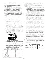
Page 2: ...ure 4 Coat V ring seal with grease to protect against ozone attack 12 Misalignment of plummer blocks must not exceed 1 2º one half degree Table 2 Recommended Torque Value Bolt Size mm 10 12 16 20 24 Grade 8 8 47 51 81 89 203 215 415 420 720 725 Stainless Steel A2 A4 Class 70 24 40 110 170 INSTALLATION USN 500 and 600 Series Adapter Mount 1 Apply a coating of light oil or other rust inhibitor to th...

Page 3: ...install V ring seal on seal ring until housing cap has been set in place and tightened b Seal Ring Install a seal ring on shaft with largest O D toward bearing c Bearing Install bearing Bearings with cylindrical bore up to 70 mm may be cold mounted on the shaft Apply coat of light oil to the shaft and bearing bore then press on the bearing by mechanical or hydraulic device or use the mounting nut ...

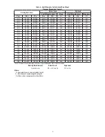
Page 4: ...85 000 84 980 85 035 85 013 034 85 045 85 023 044 90 90 000 89 980 90 035 90 013 034 90 045 90 023 044 95 95 000 94 980 95 035 95 013 034 95 045 95 023 044 100 100 000 99 980 100 035 100 013 034 100 045 100 023 044 110 110 000 109 980 110 035 110 013 034 110 045 110 023 044 120 120 000 119 980 120 035 120 013 034 120 045 120 023 044 130 130 000 129 975 130 040 130 015 040 130 052 130 027 052 140 1...

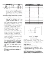
Page 5: ...the center seal ring groove of the housing Shaft should not extend beyond locknut end to ensure no rubbing with end plug or housing on cast closed end 8 Grease the bearing seal grooves in the housing cap and place over the bearing after wiping the mating surfaces does not apply for oil lubricated bearings The two dowel pins will align the cap with the lower housing half Note Each cap must be match...

Page 6: ...e RPM exceeds 80 of maximum RPM do not add grease in the lower half of the housing nor in the cap At each regreasing cycle for applications up to 80 of maximum RPM slowly add grease until fresh grease is seen purging at the seals Regreasing should be done while running Remote re greasing lines should be added to avoid endangering personnel If the RPM is greater than 80 of maximum RPM add 4 strokes...

Page 7: ... and tapped drain hole on the side of the plummer block for visual indication of this level The oil level may drop or rise during operation depending on the rotation of the bearing Oil should be added only when the bearing is not operating Both the static oil level and the running oil level should be marked on the oil sight gauge and properly identified Prior to installation on the structure if th...

Page 8: ...300 55 22211 C3 4500 5600 60 22212 C3 4000 5000 65 22213 C3 3600 4500 70 22314 C3 2400 3200 75 22215 C3 3400 4300 80 22216 C3 3200 4000 85 22217 C3 3000 3800 90 22218 C3 2600 3400 95 22219 C3 2400 3200 100 22220 C3 2200 3000 110 22222 C3 2000 2800 120 22224 C3 1800 2400 130 22226 C3 1700 2200 140 22228 C3 1600 2000 150 22230 C3 1500 1900 160 22232 C3 1400 1800 ...

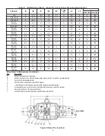
Page 9: ...9 15 280 45 8 320 74 18 M16 524 224 620 320 79 5 48 5 17 5 290 45 8 330 74 18 M16 526 226 622 322 82 5 53 19 325 52 12 370 80 22 M20 528 228 88 5 64 5 19 345 55 12 400 92 26 M24 530 230 624 324 97 5 64 5 20 5 375 60 12 430 100 26 M24 532 232 626 326 104 65 23 395 60 12 450 100 26 M24 Notes on Table 11 All dimensions are in millimeters Item Description A Optional location for seal lubrication B Opt...

Page 10: ...17 454 28 5 1 8 28 513 019 567 32 1 8 28 611 311 019 567 40 5 1 8 28 515 023 662 27 1 4 19 612 312 023 662 30 5 1 4 19 516 025 738 38 1 4 19 613 313 025 738 42 1 4 19 517 028 757 34 5 3 8 19 314 028 757 37 3 8 19 518 030 946 34 5 3 8 19 615 315 030 946 42 3 8 19 519 616 316 038 1 13 47 3 8 19 520 042 1 32 39 5 3 8 19 617 317 042 1 32 42 3 8 19 522 619 319 057 1 59 45 3 8 19 524 066 1 82 53 5 1 2 1...

Page 11: ...5 039518 046187 046188 046189 046190 046191 046192 046193 17 V Ring 2 042224 042225 042225 042226 042227 042228 042228 042228 042230 042230 042230 042232 042232 042233 042234 042235 042235 18 Non Expansion Spacer 1 046458 042335 042315 046440 042316 041174 041172 041175 041173 046643 041176 041177 041185 041178 041179 041186 041180 20 Adapter Sleeve 1 046265 046266 046267 046268 046269 046270 0462...

Page 12: ...547 046181 046338 046183 046184 046548 046341 046188 046189 046190 17 V Ring 2 042243 042224 040972 042225 042226 042226 045994 042228 042229 042230 045965 042231 042233 042233 18 Non Expansion Spacer 1 042335 042315 046642 042316 460886 460887 460889 046643 460890 460891 460892 460635 042341 460896 20 Adapter Sleeve 1 046652 046653 046654 046655 046656 046657 046658 046659 046660 046661 046662 04...

Page 13: ... 2 046459 046181 046170 046181 046171 046172 046175 046453 046174 046342 046190 046191 046192 046454 046455 046456 046457 17 V Ring S2 2 042226 042226 042228 042226 042229 042230 042230 042231 042231 042231 042233 042234 042235 042236 042237 042237 042238 18 Non Expansion Spacer 1 041987 042335 042315 046642 042316 041174 041172 041275 041173 046643 041176 041177 041185 041178 041179 041186 041180...

Page 14: ...Seal Ring S2 2 046179 035743 046181 046338 046183 046340 046549 039518 046341 046342 046189 046190 046191 046192 045990 17 V Ring S2 2 042225 040972 042226 045994 042228 042229 042230 042230 045965 042231 042232 042233 042234 042235 042236 18 Non Expansion Spacer 1 042335 042315 046642 042316 460886 460887 460888 460889 046643 460890 460891 460892 046635 042314 460896 22 Locknut 1 046492 046285 04...

Page 15: ...15 ...

Page 16: ... Fort Smith AR 72901 Ph 1 479 646 4711 Mechanical Power Transmission Support Ph 1 864 297 4800 new abb com mechanical power transmission baldor com ABB Motors and Mechanical Inc MN3066 Replaces 499801 499809 All Rights Reserved Printed in USA 11 19 3066 1119 ...

Reviews: