32
DPA 2 50 S 4 50 - 2 50 K W
O P ER AT I N G M A N UA L
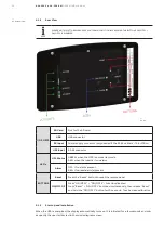
5.1.2
Rear View
NOTE
PLEASE NOTE THAT THE EMERGENCY SHUTDOWN FUNCTION BY PRESSING THE BUTTONS ON/OFF 1 +
ON/OFF 2 IS DISABLED
—
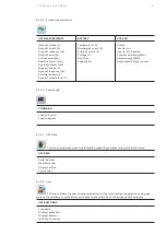
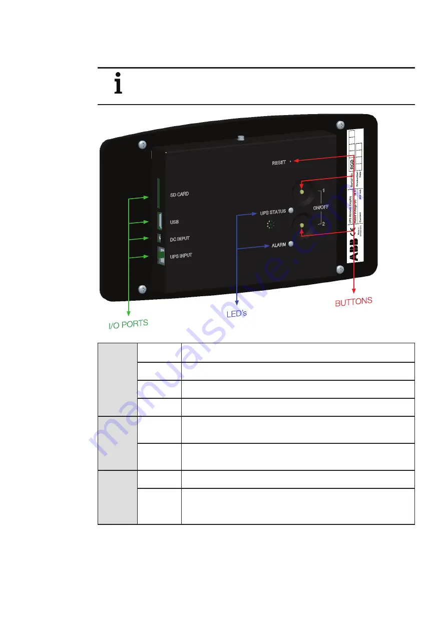
5.1.2-1: Rear view
—
5.1.2-1
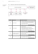
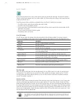
I/O PORTS
SD Card
Slot for the SD card
USB
USB connector
DC Input
Power supply connector (only needed if the RJ-45 cable is >75 & <100m)
UPS Input
RJ-45 connector
LED’s
UPS Status
GREEN: when the UPS is on inverter mode
RED: when the inverter is on alarm
Alarm
OFF: if no alarm present
RED: if unread alarm(s) present
BUTTONS
Reset
Press the “Reset” button to reset the remote panel
ON/OFF 1/2
Press “ON/OFF 1” + “ON/OFF 2”: Function disabled
Press “Reset” + “ON/OFF 1” buttons simultaneously, then release "Reset"
and hold the "ON/OFF 1" button for 10 seconds: Touch screen calibration
5.1.3
Start up and installation
When the UPS is energized, the display automatically turns on. It is initiated for a few seconds and sub-
sequently the user is directed to the mimic diagram screen.

