35
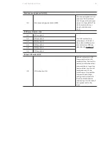
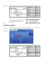
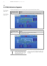
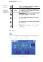
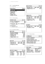
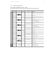
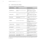
The color of each block identifies its functional status. There are four main colors in the mimic diagram:
• Green: In operation
• White: Inactive block
• Yellow: Warning condition
• Red: Fault condition
Device
Color meaning
Rectifier
Green:
Rectifier is on.
Red:
Rectifier is switched off.
Inverter
Green:
Load is on inverter.
Red:
Inverter is switched off.
Bypass
Green:
Load is on bypass
White:
Bypass is switched off.
Battery
Green:
Battery is charging or discharging.
Yellow:
Battery is low.
Red:
Battery is in fault condition or is discharged.
Arrows indicate if battery is charging or discharging.
Maintenance Bypass Q1
Yellow:
Load is on maintenance bypass
White:
Maintenance bypass opened
Output Breaker Q2
Green:
UPS output breaker is closed (Position ON)
Red:
UPS output breaker is opened (Position OFF)
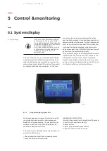
Touching the functional blocks in the mimic diagram, the measurements related to the object selected
are displayed.
5.1.5.2 Module selection
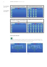
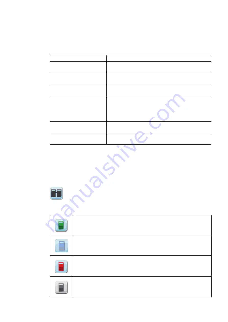
By pressing the icon Module selection, the user starts the navigation (status and measure-
ments) on the UPS module level. The module selection screen will show the amount of UPS modules in
the system and the status as follows:
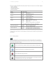
Active. The UPS module is running in double conversion,bypass or battery mode.
Standby. The UPS module is in standby mode (inverter OFF).
Alarm. UPS module with general alarm.
Module switched OFF (load-OFF), but physically present in the frame. (If a module is
not physically present in the frame, no icon appears).
5 CO N T R O L & M O N I TO R I N G

