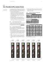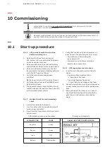
79
10 CO M M I SS I O N I N G
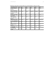
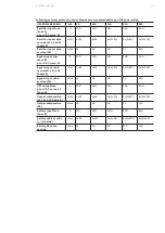
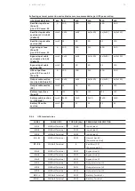
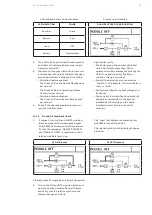
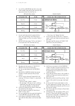
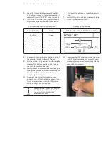
LED indicators status on all modules
Display on all modules
LED INDICATION
COLOR
DUAL INPUT FEED CONFIGURATION
Rectifier
Green
Bypass
Red
Load
OFF
Battery
Flashing Red
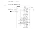
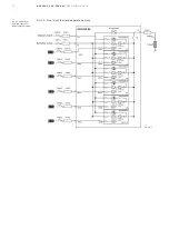
4. The 3 LEDs (Orange, Red and Green) present
on all Parallel Interface boards (one in each
frame) must be OFF.
5. The status of the green led on the Customer
Interface board (one in each frame) changes
according to the Multidrop feature setting.
• Multidrop feature enabled:
The Green LED on the frame 1 flashes once
per second.
The Green LEDs in all remaining frames
flash twice per second.
• Multidrop feature disabled:
The Green LED on all frames flashes once
per second.
6. Check if the operating parameters are cor-
rectly set in all modules.
In particular verify:
• The battery type, the number of blocks/
cells, and the autonomy time. Other
parameters will be automatically set by the
UPS (if no special battery floating or
minimal voltage is required).
• Check if the batteries are connected as
“Common” or “Separate” (Common Battery
«Yes» or «No»).
• Verify the settings for output voltage and
frequency.
• Correctly set the identification number of
all frames and modules in the parallel
installation (All modules on the same
installation must have a univocal Id.
number).
10.1.4 Q1 and Q2 feed-back check
1.
If present, turn to ON and to OFF position
(close and open) the maintenance bypass
switch
Q1
on all frames one at time and ver-
ify that the messages “MAN BYP CLOSED”
and “MAN BYP OPEN” is registered on the
relative module(s) event log.
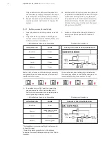
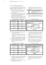
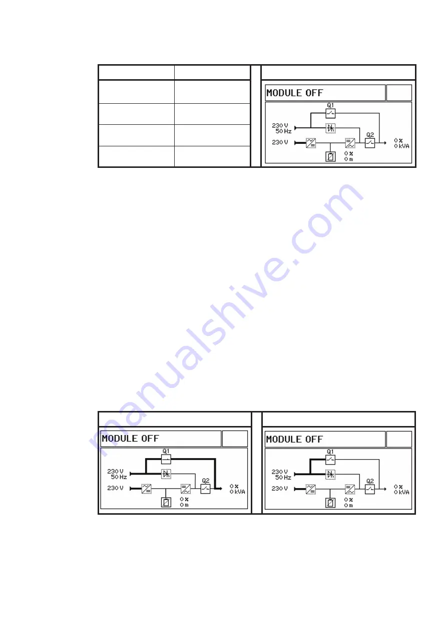
The “Load” led indicator becomes yellow
when
Q1
is in the ON position.
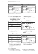
The relative symbol on the display changes
as follow:
Q1 ON (Closed)
Q1 OFF (Opened)
Display in case of single input feed configuration.
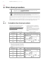
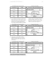
2. Turn to the ON and OFF position (close and
open) the output isolator Q2 on all frames
and verify that the relative symbol on the
display changes as follows:

