ACH550-UH User’s Manual
93
Group 26: Motor Control
This group provides controls for fine-tuning the motor control.
Group 26: Motor Control
Code Description Range
Resolution
Default
S
2601
FLUX OPTIMIZATION
0…1
1
1
Changes the magnitude of the flux depending on the actual load. Flux Optimization can reduce the total energy
consumption and noise, and should be enabled for drives that usually operate below nominal load.
0 =
OFF
– Disables the feature.
1 =
ON
– Enables the feature.
2602
FLUX BRAKING
0…1
1
0
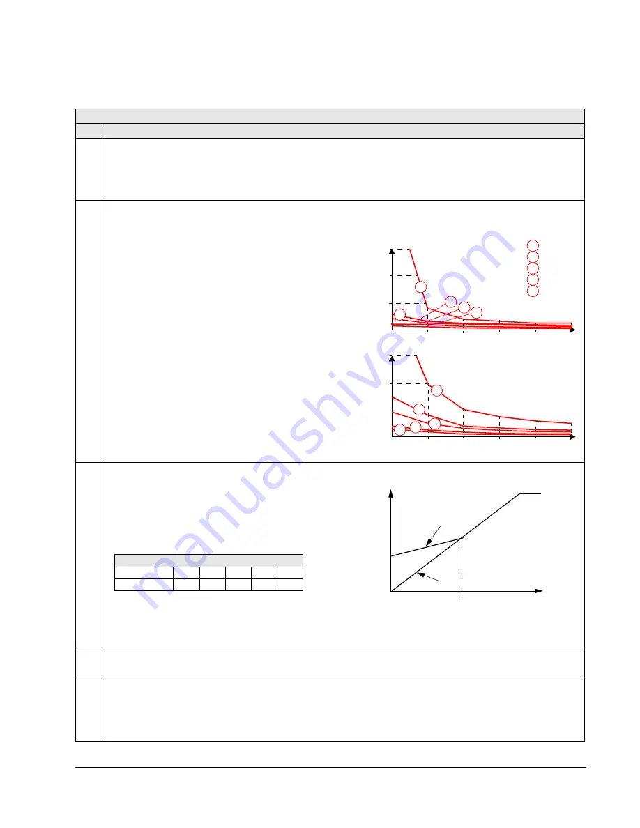
Provides faster deceleration by raising the level of
magnetization in the motor when needed, instead of limiting
the deceleration ramp. By increasing the flux in the motor,
the energy of the mechanical system is changed to thermal
energy in the motor.
0 =
OFF
– Disables the feature.
1 =
ON
– Enables the feature.
2603
IR COMP VOLT
0.0…100.0 V
0.1
0.0
Sets the IR compensation voltage used for 0 Hz.
• Requires parameter 9904
MOTOR
CTRL
MODE
= 3
(
SCALAR
SPEED
).
• Keep IR compensation as low as possible to prevent
overheating.
• Typical IR compensation values are:
IR Compensation
• When enabled, IR Compensation provides an extra
voltage boost to the motor at low speeds. Use IR Compensation, for example, in applications that require a high
breakaway torque.
2604
IR COMP FREQ
0…100%
1
80
Sets the frequency at which IR compensation is 0 V (in % of motor frequency).
2605
U/f RATIO
1, 2
1
2
Selects the form for the U/f (voltage to frequency) ratio below field weakening point.
1 =
LINEAR
– Preferred for constant torque applications.
2 =
SQUARED
– Preferred for centrifugal pump and fan applications. (Square is more silent for most operating
frequencies.)
120%
80
40
0
W/O Flux Braking
50
With Flux Braking
5
10
20
30
40
120%
80
40
0
50
5
10
20
30
40
1
2
3
4
5
1
2
3
4
5
1
2
3
4
5
2.2 kW
15 kW
37 kW
75 kW
250 kW
Rated Motor Power
Braking
f (Hz)
f (Hz)
Torque (%)
Motor
f (Hz)
A
B
Voltage
A = IR Compensated
B = No compensation
P 2603
P 2604
380…480 V Units
P
N
(kW)
3
7.5
15
37
132
IR comp (V)
21
18
15
10
4


