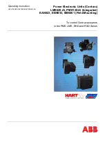
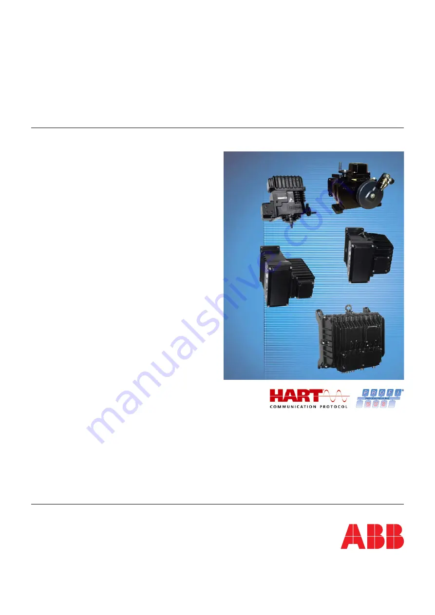
background image


Operating Instruction 

OI/PME/LME/EAN823/EBN853/EBN861-EN 


Power Electronic Units (Contrac)

LME620-AI, PME120-AI (Integrated) 

EAN823, EBN853, EBN861 (Field-Mounting)


To control Contrac actuators

in the PME, LME, RHD and RSD Series


Summary of Contents for EAN823

Page 1: ...Instruction OI PME LME EAN823 EBN853 EBN861 EN Power Electronic Units Contrac LME620 AI PME120 AI Integrated EAN823 EBN853 EBN861 Field Mounting To control Contrac actuators in the PME LME RHD and RS...

Page 2: ...rstra e 72 32425 Minden Germany Tel 49 551 905 534 Fax 49 551 905 555 Customer service center Phone 49 180 5 222 580 Fax 49 621 381 931 29031 automation service de abb com Copyright 2010 by ABB Automa...

Page 3: ...function 12 2 1 Modules 13 2 1 1 LME620 AI PME120 AI electronic unit EAI823 13 2 1 2 EAN823 EBN853 14 2 1 3 EBN861 15 2 2 Factory default 16 2 2 1 Standard control 16 2 2 2 Profibus DP communication 1...

Page 4: ...8 Correcting your settings 30 6 1 9 Manual MAN and automatic AUT mode software version 2 00 and higher 30 6 1 10 Signals on the commissioning and service field ISF 31 6 2 Positions for the potential s...

Page 5: ...oduct may only be performed if expressly permitted by these instructions Only by observing all of the safety instructions and all safety warning symbols in these instructions can optimum protection of...

Page 6: ...ury WARNING Bodily injury This symbol in conjunction with the signal word Warning indicates a possibly dangerous situation Failure to observe this safety information may result in death or severe inju...

Page 7: ...connection 1 Electronic unit type 2 Serial no NL no no of non list version 3 Permissible voltage range year of manufacture 4 Permissible line frequency max power consumption 5 Permissible ambient temp...

Page 8: ...d aggressive condition for a short time The equipment is protected against external corrosive influences However direct exposure to rain snow etc must be avoided The permissible storage and transport...

Page 9: ...se the type of electrical protection may be adversely affected Safe isolation of electrical circuits which are dangerous if touched is only guaranteed if the connected devices satisfy the requirements...

Page 10: ...ease Please contact Customer Center Service acc to page 2 for nearest service location 1 12 Integrated management system ABB Automation Products GmbH operates an integrated management system consistin...

Page 11: ...accept and dispose of returns for a fee 1 13 2 RoHS Directive 2002 95 EC With the Electrical and Electronic Equipment Act ElektroG in Germany the European Directives 2002 96 EC WEEE and 2002 95 EC RoH...

Page 12: ...Design and function 12 OI PME LME EAN823 EBN853 EBN861 EN 2 Design and function Fig 4 Concept example with separate electronic unit...

Page 13: ...actuators with integrated electronic unit PME120 AI and LME620 AI consist of 2 components One component is the gearing which includes the connection components and the transformer The other component...

Page 14: ...onic unit cover 3 Cover for commissioning and service field ISF 4 Holes for cable glands 5 Cover for connection space Fig 7 Connection area 1 Fuse protection against active feed at 20 mA setpoint inpu...

Page 15: ...ctronic unit cover 3 Cover for commissioning and service field ISF 4 Cover for connection space 5 Holes for cable glands Fig 9 Connection area 1 Commissioning and service field ISF 2 Hinge screws 3 Co...

Page 16: ...rve rated torque force Setpoint function Linear setpoint position value Setpoint input 4 20 mA Function selection Positioner parameter setpoint Positioning time out disabled Actual output value 4 20 m...

Page 17: ...laced on both housings when connecting the electronic unit and the actuator 3 1 LME620 AI PME120 AI Important Notice For information about the installation of actuators with integrated electronic unit...

Page 18: ...ard while lifting it up and off the hinge pins The cover of the electronic unit must be positioned in exactly the right place For details about how to install the housing half see section Mounting Mou...

Page 19: ...mp pins Terminals Option Motor heater 1 5 mm2 16 AWG Wire cross sectional area Signals 0 5 mm2 20 AWG Motor heater signals 0 2 2 5 mm2 24 14 AWG Contact surface Motor signal Gold plated Heater Silver...

Page 20: ...he connectors 2 Cut the cable sheath 3 to the required length 3 Separate the shield and peel it back to its inner sheathing 4 4 Push the cable through the cable gland and fasten it with the clamp 1 5...

Page 21: ...mproper installation Do not clamp individual wires under the clip Important Notice To prevent interference from electromagnetic fields the signal and power cables in the connector housing must be rout...

Page 22: ...es are connected by universal plug to the integrated actuator electronic unit Fig 12 4 4 1 2 PROFIBUS DP M00250 DO1 endp 0 DO2 endp 100 mains 1 13 L N B1 B2 A1 A2 S1 ext fuse Bus in bus connection Han...

Page 23: ...W Br Br 1 2 1 2 3 13 14 M 3 H1 H2 PE 28 29 24V 30 RB 31 I U 26 27 1 7 2 8 3 9 4 10 13 5 11 14 6 12 15 L N M00062 sub distribution board mains ext fuse Screen connected to both ends one sided screenin...

Page 24: ...Electrical connections 24 OI PME LME EAN823 EBN853 EBN861 EN 4 4 2 2 PROFIBUS DP Fig 15...

Page 25: ...sectional area between the fuse and the electronic unit must be a minimum of 2 5 mm AWG 14 Fig 16 1 External fuse 35 A 2 External fuse 16 A Fig 17 4 5 Configuration of digital input output signals st...

Page 26: ...roller pulses instead of an analog setpoint The following conditions must be fulfilled in order to implement the step controller pulses Digital input function Step controller has been selected The act...

Page 27: ...ISF It can be used to adjust the actuator to the working area and set the direction without using a PC The actuator can be further parametrized using a graphic user interface Important Notice The com...

Page 28: ...position as 0 press in combination with the 2 button to end the adjustment process By simultaneously pressing the 2 button for at least 5 seconds you can switch the actuator to manual mode MAN Softwa...

Page 29: ...actuator The electronic unit is in MAN mode no signal at digital input 1 DI 1 No error if an error is pending the LEDs will flash alternately at 4 Hz 6 1 2 Opening the cover flap of the ISF Release th...

Page 30: ...a correction press the reset button 3 and repeat the setting procedure If you need to make a correction after saving your settings you will need to repeat the entire setup procedure from the beginnin...

Page 31: ...LED 10 is on LED 5 is off Normal operation MAN via ISF LED 10 is off LED 5 flashes at 1 Hz Normal operation AUT The LEDs are off Positioning via the button on the ISF takes priority over the control s...

Page 32: ...the reference potential either to the system or the protective ground see page 28 Fig 20 item 8 Name INT Position A SYS Position B Settings Conventional control via analog setpoint without external e...

Page 33: ...ion chamber 40 mA fast acting Brake fuse 5 x 20 mm Power board 0 315 A medium time lag DC link fuse 6 3 x 32 mm Power board 10 A super fast acting EBN853 Heater optional 5 x 20 mm in connection chambe...

Page 34: ...e electronic unit Use the graphic user interface to read out stored alarms 7 1 2 Error The actuator or electronic unit is in a critical state e g positioning time out which currently is impairing the...

Page 35: ...re Temperature of Electronic Unit upper limit lower limit upper limit lower limit Lubricant Elastom Motor Gear high low high low Monitoring ON Integr controller ON Behavior at critical temp MAN AUT Ac...

Page 36: ...till Min speed Movement in incorrect direction Frequency converter end positions Position sensor memory error Flash error RAM error Watchdog monitoring activated Monitoring ON Error signal Error messa...

Page 37: ...k Binary inputs on the electronic unit are not wired Make connection The actuator does not respond Brake does not release no mechanical click Check the brake air gap approx 0 25 mm 0 010 inch and elec...

Page 38: ...rox 40 50 of lmax External fuse 16 A time lag Power Electronic Unit EBN853 Contrac Ingress protection IP 66 acc to IEC 60529 EN 60529 NEMA 4X acc to CAN CSA22 2 No 94 Humidity 95 annual average conden...

Page 39: ...10 1 Conventional communication Analog input 0 4 20 mA internal load EAI823 EAN823 EBN853 300 internal load EBN861 250 Analog output 0 4 20 mA electrically isolated max load 500 3 digital inputs BE 1...

Page 40: ...o safety position Rules with last effective setpoint Adjustable time delay Modules for cyclical communication 8 standards compliant modules and 3 manufacturer specific modules are available SP Short S...

Page 41: ...art Turn Actuators PME120 RHD250 4000 OI PME RHD250_4000 Operating Instructions for Electrical Part Turn Actuators RHD8000 16000 OI RHD8000_16000 Operating Instructions for Electrical Linear Actuators...

Page 42: ...Appendix 42 OI PME LME EAN823 EBN853 EBN861 EN...

Page 43: ...n Telephone Fax E mail Device details Type Serial no Reason for the return description of the defect Was this device used in conjunction with substances which pose a threat or risk to health F Yes F N...

Page 44: ...xternal fuse for EBN861 25 External fuses 25 F Factory default 16 Failure 31 Fuse type 33 Fuses 25 G General information and notes for the reader 5 General information on operation 27 H Hazardous mate...

Page 45: ...period 8 T Target groups and qualifications 5 Terminal connection diagrams 20 22 Transport 8 Transport safety information 8 Transport temperatures 8 Trouble shooting 37 Typical commissioning with the...

Page 46: ...in without notice Printed in the Fed Rep of Germany 10 2010 ABB 2010 3KXE181008R4201 OI PME LME EAN823 EBN853 EBN861 EN ABB Limited Salterbeck Trading Estate Workington Cumbria CA14 5DS UK Tel 44 0 19...

Reviews: