100
EL3000
CONTINUOUS GAS ANALYZERS | OI/EL3000-EN REV. D
… 6 Electrical connections
Connecting the Signal Lines
Safety instructions
• Follow local regulations on installing and connecting
electrical wiring.
• Lay the signal lines separately from the power supply lines.
• Lay analog and digital signal lines separately from each
other.
• Label cables or counter plug so that they can be clearly
allocated to the corresponding I/O modules.
Requisite Material
Refer to
on page 16.
Connecting the Signal Lines
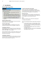
1. Only for the wall-mounted housing (model EL3040):
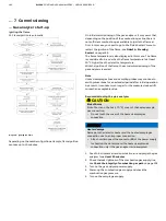
Feed the cables through the cable glands and strip them over
a length of approx. 18 cm, see
on page 95.
• M20 and M32 cable gland:
Remove the plug from the insert; leave the ring in the
gland to act as a gasket and to provide strain relief.
• Cable gland M25:
Remove the plug from the gland. Remove the drilled
insert from the accessory bag and if necessary, slit it
open and press it over the cable; close any free drill holes
with dowel pins from the accessory bag.
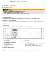
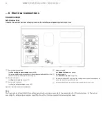
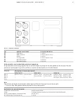
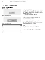
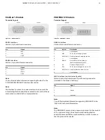
2. Connect the cables to the opposite connectors, according to
the connection diagrams of the I/O modules.
• Analog output module, see
page 96
• Digital-I/O module, see
3. Connect the opposite connectors to the plug-in terminal
strips on the I/O modules.
Connecting the power supply
NOTICE
Damage to the gas analyzer
Damage to the gas analyzer due to condensing sample gas
during commissioning.
• Observe the condition of the sample gas inlet of the
analyzer modules.
• Purge the sample gas path before commissioning, see
Purge sample gas path and analyzer housing
on page 103.
• Do not connect the sample gas until the gas analyzer has
reached room temperature and after the warm-up phase
has elapsed, see
page 103.
NOTICE
Heater damage
Damage to the detector heater and the heated sample gas
connection due to an improper connection.
• Attach or disconnect the connector
30
of the power supply
for heating the detector and the heated sample gas
connection only if the gas analyzer is de-energized.
Requisite Material
If the supplied mains lead is not used, select conductive material
which is appropriate for the length of the lines and the
predictable current load.
Potential equalization
The gas analyzer has a terminal marked with the symbol for
connection with the building-side potential equalization. The
connector has a clamping range of max. 4 mm
2
.

