background image


— 

A B B  M EA S U R EM ENT  &  A NA LY TIC S   |  O PERA TING  INS TR U C TIO N  |  O I/ EL3 0 0 0 - E N  R EV . D  

EasyLine EL3000 

Continuous gas analyzers 


— 
ABB Measurement & Analytics 

 
For your local ABB contact, visit: 

www.abb.com/contacts 
 

For more product information, visit: 

www.abb.com/analytical 


So smart, they're simple 

Measurement made easy 


O

I/

EL

3000

-EN

 R

ev.

 D


0

7.

20

21


— 
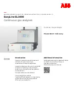
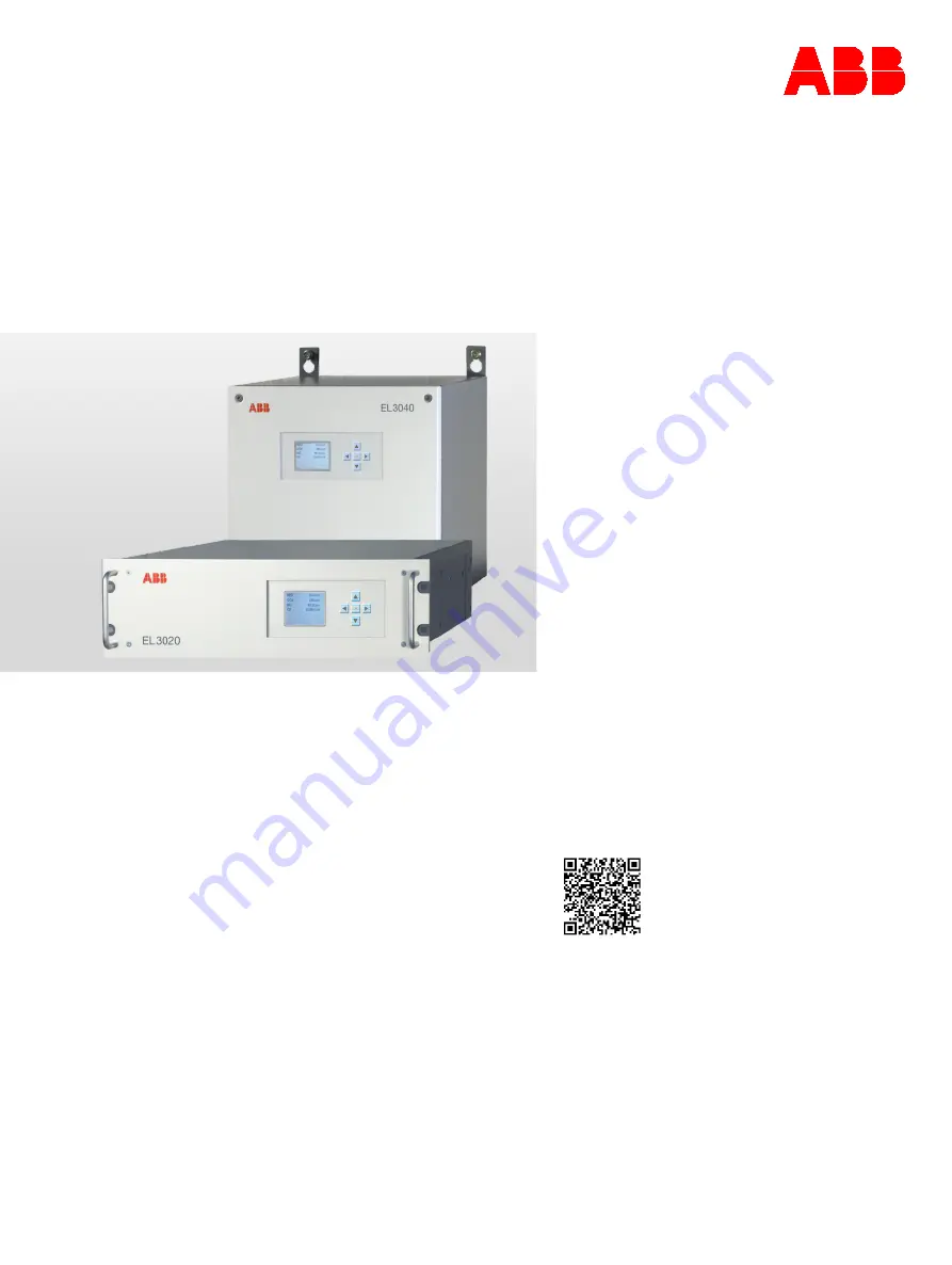
EasyLine EL3020 
EasyLine EL3040 

Introduction 

EasyLine is a powerful yet cost-effective line of 
devices for the measurement of gas 
concentrations in numerous applications. 
 
Automatic calibration and the use of superior ABB 
calibration cell technology in the photometer 
avoids the use of expensive test gas cylinders in 
most applications. 
Zero-point calibration with ambient air 
 
Various analyzer types available: 
Combining different analyzers in a single housing 
enables optimum economy and operational 
efficiency for your application. 


Additional Information 

Additional documentation on EasyLine EL3000 is 
available for download free of charge at 
www.abb.com/analytical. 
Alternatively simply scan this code: 


— 
We reserve the right to make technical changes or modify the contents of this document 
without prior notice. With regard to purchase orders, the agreed particulars shall prevail.  
ABB does not accept any responsibility whatsoever for potential errors or possible lack of 
information in this document.  
 
We reserve all rights in this document and in the subject matter and illustrations contained 
therein. Any reproduction, disclosure to third parties or utilization of its contents – in whole 
or in parts – is forbidden without prior written consent of ABB. 
 
© ABB 2021 

3KXG112001R4201 


Summary of Contents for EasyLine EL3000

Page 1: ...utomatic calibration and the use of superior ABB calibration cell technology in the photometer avoids the use of expensive test gas cylinders in most applications Zero point calibration with ambient air Various analyzer types available Combining different analyzers in a single housing enables optimum economy and operational efficiency for your application Additional Information Additional document...

Page 2: ...ne 88 Fidas24 Connecting the sample gas line to the heated sample gas connection 89 Fidas24 Connecting the sample gas line to the unheated sample gas connection 91 6 Electrical connections 93 Safety instructions 93 General Notes 93 Model EL3020 93 Model EL3040 94 Analog output modules 96 Digital I O module 97 Modbus Module 99 PROFIBUS Module 99 Connecting the Signal Lines 100 Connecting the power ...

Page 3: ...tions 164 The Dynamic QR Code 164 Status messages Explanations 166 Status messages on the LCD display 167 Possible status messages 168 Troubleshooting 173 Fidas24 Troubleshooting 174 Notify Service 176 Returning devices 176 13 Maintenance 177 Safety instructions 177 Inspection 177 Maintenance switch 178 Perform calibration reset 178 Uras26 Limas23 measuring the calibration cell 179 Limas23 Intensi...

Page 4: ...must be fully legible at all times The operating company must strictly observe the applicable national regulations relating to the installation function testing repair and maintenance of electrical products Warnings The warnings in these instructions are structured as follows DANGER The signal word DANGER indicates an imminent danger Failure to observe this information will result in death or seve...

Page 5: ...peration in hazardous areas DANGER Explosion hazard Explosion hazard when measuring flammable gases in hazardous areas The gas analyzer in the explosion proof design model EL3040 may only be used for the measurement of non flammable gases and vapors The model EL3040 gas analyzer is available in explosion proof design with degree of protection II 3G see Use in potentially explosive atmospheres on p...

Page 6: ...rotective lead connector before any other connection is made Risks of a disconnected protective lead The device can be hazardous if the protective lead is interrupted inside or outside the device or if the protective lead is disconnected Potential equalization The external potential equalization connection of the analyzer housing must be connected to the local potential equalization The local pote...

Page 7: ...not escape to the outside Conditions to be complied with by the end user The end user must comply with the following prerequisites and conditions to ensure safe operation of the gas analyzer The gas analyzer may be used for the measurement of flammable gases provided that the flammable portion does not up scale 15 Vol CH4 oder C1 equivalents The relevant safety regulations for working with combust...

Page 8: ...terally adjacent built in components must be at least 4 mm If the gas analyzer is installed in a closed cabinet adequate ventilation of the cabinet must be provided at least 1 change of air per hour The distance to adjacent built in components towards the top and at the side must be at least 4 mm Notes on data safety This product is designed to be connected to and to communicate information and da...

Page 9: ...EasyLine Configuration Tool Password on page 156 This limits access to both the ECT software tool itself and to the calibration and configuration functions of the device Manufacturer s address ABB Automation GmbH Measurement Analytics Stierstädter Str 5 60488 Frankfurt am Main Germany Tel 49 69 7930 4666 Email cga de abb com Service address If the information in this Operating Instruction does not...

Page 10: ...registration devices or for which it is expressly noted in the type examination certificate Maintenance work on the device where opening the housing or part of the housing is necessary is only permitted in a non hazardous atmosphere DANGER Risk of explosion There is an explosion hazard if the housing is opened in a potentially explosive atmosphere Before opening the housing make sure that no flamm...

Page 11: ...IC T4 Gc In undisturbed operation there cannot be any sparking arcing or impermissible temperatures inside the device Explosion protection through increased safety as well as gasketed or encapsulated equipment Type examination certificate no BVS 16 ATEX E 085 X Note The measurement function of the analyzer is not part of the type examination certificate Explosion protection The gas analyzers are d...

Page 12: ... with sealing plugs If there is an explosion hazard at the installation site of the gas analyzer the housing must not be opened when live and the connectors must not be disconnected when live Due to the low mechanical stability of the viewing glass the gas analyzer must be designed and operated in such a way that mechanical damage to the viewing glass with an energy greater than 2 J can be exclude...

Page 13: ...ptionally as an explosion proof variant 1 LCD indicator 2 Gas and electrical connections Figure 1 EasyLine EL3000 housing designs The EL3020 gas analyzer model features a 19 housing with 3 HU 4 HU with Magnos27 and IP rating IP 20 IP 40 in the version for emissions monitoring The housing for the EL3040 gas analyzer model is designed as wall mount housing with an IP rating of IP 65 ...

Page 14: ...e oxygen analyzer for the measurement of O2 in pure gases N2 CO2 Ar Caldos27 thermal conductivity analyzer for the measurement of binary gas mixtures with different thermal conductivity such as Ar in O2 H2 in Ar CH4 in N2 Fidas24 flame ionization detector for the measurement of hydrocarbons Electrochemical oxygen sensor for the measurement of O2 Available analyzer combinations Analyzer combination...

Page 15: ...tion configuration and maintenance of the gas analyzer or about the Modbus and PROFIBUS interface Analyzer data sheet The design of the gas analyzer that has been supplied is documented in detail in the analyzer data sheet Material required for installation Note The materials listed below are not included in the scope of delivery of the device and must be provided by the customer Gas connections F...

Page 16: ... maximum capacity of terminals for stranded or solid conductors is 1 mm2 17 AWG The stranded conductor may be tinned on the tip or twisted for simplified connection When using wire end ferrules the total section must not exceed 1 mm2 i e the maximum stranded conductor section cannot be greater than 0 5 mm2 The Weidmüller PZ 6 5 crimping tool must be used for crimping the ferrules Lengths and types...

Page 17: ...e ambient conditions Protect the gas analyzer from the following influences Cold Exposure to heat from e g the sun furnaces boilers Temperature variations Strong air currents Accumulation of dust and ingress of dust Corrosive atmosphere Vibration Climatic Conditions Relative humidity Maximum 75 no condensation Ambient temperature During operation 5 to 45 C Uras26 in combination with another analyz...

Page 18: ...pply built into the system housing is used to supply 24 V DC to the analyzer module and the associated electronics Input voltage 100 to 240 V AC 15 10 50 to 60 Hz 3 Hz Power Maximum 187 VA without heaters from Fidas24 Connection 3 pole cold device plug in accordance with EN 60320 1 C14 Power cable included in scope of supply Battery Application Supply to the built in clock in case of a voltage fai...

Page 19: ...measurement in corrosive gases Associated gases such as chlorine Cl2 or hydrogen chlorides such as wet HCl as well as gases or aerosols containing chlorine must be cooled or pre absorbed Flammable gases In the version with gas lines and gas connectors made of stainless steel the analyzer is suited for the measurement of flammable gases in non explosive environments The special conditions when meas...

Page 20: ... or ambient air Calibration cells or span gas Uras26 Magnos27 manual calibration Zero point gas for Uras26 or Magnos27 or IR sample component free test gas with O2 concentration in an existing measuring range or ambient air Span gas for all sample components in Uras26 and Magnos27 Uras26 Caldos27 automatic calibration i e Caldos27 with single point calibration IR sample component free test gas wit...

Page 21: ...ow rate of 60 l h Permissible absolute pressure range 800 to 1250 hPa Operation under lower absolute pressure e g at altitudes above 2000 m on request Gauge pressure in the sample cell max 500 hPa Flow rate 20 to 100 l h Corrosive gases The analyzer may not be used for measurement in corrosive gases Associated gases such as chlorine Cl2 or hydrogen chlorides such as wet HCl as well as gases or aer...

Page 22: ...ith calibration cells automatic calibration i e Magnos206 Magnos28 with single point calibration N2 or oxygen and UV sample component free gas Either calibration cells and test gas for oxygen detector or test gas for each sample component or for each detector Limas23 Magnos206 Magnos28 or oxygen sensor without calibration cells automatic calibration N2 or oxygen and UV sample component free gas Te...

Page 23: ...ressure sensor must be connected to the sample gas path The pressure compensation must be calculated externally The analyzer module is function tested for 5000 hPa internal pressure without damage Flow rate 30 to 90 l h Abrupt changes in the sample gas flow rate should be avoided when using highly suppressed measurement ranges Corrosive gases If the sample gas contains Cl2 HCl HF or other corrosiv...

Page 24: ...le point calibration 100 Vol O2 or test gas with O2concentration in the measuring range Test gas with O2 concentration near the end point of the measuring range Magnos206 with single point calibration Test gas with O2 concentration in an existing measuring range or ambient air Magnos206 with substitute gas calibration Oxygen free process gas or substitute gas O2 in N2 Substitute gas for example dr...

Page 25: ...module is function tested for 5000 hPa internal pressure without damage Flow rate 30 to 90 l h measuring ranges 0 to 3 vol O2 60l h For highly suppressed measuring ranges and measuring ranges of 0 to 3 vol O2 changes of the sample gas flow should be avoided Corrosive gases If the sample gas contains Cl2 HCl HF or other corrosive components the analyzer may only be used if the sample gas compositio...

Page 26: ... Test gas with O2 concentration in an existing measuring range or ambient air Magnos28 with substitute gas calibration Oxygen free process gas or substitute gas O2 in N2 Substitute gas for example dried air Magnos28 Caldos27 manual calibration In addition to the above mentioned test gases for Magnos28 additional test gases are needed for the calibration of Caldos27 The requirements are shown in th...

Page 27: ...tandard flow rate of 60 l h Permissible absolute pressure range 800 to 1250 hPa Operation under lower absolute pressure e g at altitudes above 2000 m on request Gauge pressure in the measuring chamber max 500 hPa Flow rate 20 to 90 l h Pressure sensor The pressure sensor is optionally installed in the gas analyzer see Pressure sensor on page 36 The pressure sensor is connected to a connection sock...

Page 28: ... module is suitable for measuring flammable gases in a non explosive environment The concentration of flammable gases in the sample gas must not exceed 100 ppm Associated gas effect Inert gases Ar N2 have no effect Flammable gases CO H2 CH4 in stoichiometric concentrations to the oxygen content conversion O2 20 of the stoichiometric conversion If higher concentrations of flammable gases are presen...

Page 29: ... valves suitable for the oxygen trace measurement as required A Reference air B Stainless steel pipe C FPM hose 1 Sampling point with primary shut off valve 2 Multi way ball valve 3 3 2 way ball valve 4 Fine control and shut off valve 5 Flowmeter with needle valve and fault signalling contact f Air filter g Gas analyzer h Flowmeter without needle valve with fault signalling contact i Purge gas cyl...

Page 30: ... from the ambient air Bypass The gas analyzer is connected to a gas flow in the bypass at a constant flow rate approx 30 l h The needle valve is installed upstream of the branch to the gas analyzer and the bypass flowmeter downstream of the branch to the gas analyzer The gas analyzer draws gas flow 8 l h An excess of approx 20 l h remains If several ZO23 analyzer modules are supplied with gas in p...

Page 31: ... to 1250 hPa Operation under lower absolute pressure e g at altitudes above 2000 m on request Gauge pressure in the measuring chamber max 100 hPa Flow rate Typically 10 to 90 l h minimum 1 l h Corrosive gases If the sample gas contains Cl2 HCl HF SO2 NH3 H2S or other corrosive components the analyzer may only be used if the sample gas composition has been taken into account by the manufacturer for...

Page 32: ...dos27 Magnos28 automatic calibration Same as manual calibration with the following limitation Zero point and single point calibrations are performed for all sample components simultaneously since for thid purpose only one common digital output can be used for valve control unlike with end point calibration for this purpose Automatic calibration settings on page 119 This results in limitations with...

Page 33: ...re Flammable gases The gas analyzer may be used for the measurement of flammable gases provided that the flammable portion does not up scale 15 Vol CH4 or does not up scale C1 equivalents Further properties of the sample gas The sample gas must not be explosive at any time The analyzer module must not be used for the measurement of gases containing organometallic compounds e g lead containing fuel...

Page 34: ...must be limited to a maximum of 10 l h H2 or 25 l h H2 He mixture For this purpose the operator has to provide suited measures outside the gas analyzer ABB recommends using a bulkhead fitting with an integrated flow restrictor to be installed in the combustion gas supply line This bulkhead fitting can be supplied by ABB Combustion gas H2 order number 8329303 Combustion gas H2 He mix order number 0...

Page 35: ...ons See sections Gas connections and electrical connections Fidas24 model EL3020 on page 83 and Gas connections and electrical connections Fidas24 model EL3040 on page 84 Sample gas input and output conditions Analyzers Analyzer Additional Information Uras26 See page 19 Limas23 See page 21 Magnos206 See page 23 Magnos28 See page 27 Magnos27 See page 25 ZO23 See page 28 Caldos27 See page 31 Fidas24...

Page 36: ...easuring flammable or ignitable gases with the pressure sensor The pressure sensor must not be connected to the sample gas path if the sample gas contains flammable or ignitable components NOTICE Damage to the pressure sensor Damage to the pressure sensor by corrosive gases For the measurement of corrosive gases the terminal of the pressure sensor must not be connected to the sample gas path Prior...

Page 37: ...ity based on ISO 8573 1 Class 3 i e particle size max 40 µm oil content max 1 mg m3 dew point max 3 C Note For Uras26 the purge gas must not contain any fractions of the sample components Any sample components in the purge gas can cause false readings Initial purging upon commissioning Housing purge Purge gas Nitrogen Purge gas flow Maximum 200 l h Purge time Approx 1 hour Not for Fidas24 see for ...

Page 38: ...38 EL3000 CONTINUOUS GAS ANALYZERS OI EL3000 EN REV D 4 Preparation for Installation Dimensions 19 housing model EL3020 Dimensions in mm in Figure 3 19 housing model EL3020 ...

Page 39: ...h Magnos27 Dimensions in mm in Figure 4 19 housing model EL3020 with Magnos27 Note Only the front view of the housing with its height differing from the standard dimension is depicted in this dimensional drawing Additional views and dimensions of the 19 housing are shown in Figure 3 ...

Page 40: ...INUOUS GAS ANALYZERS OI EL3000 EN REV D 4 Preparation for Installation Dimensions Wall mount housing model EL3040 Dimensions in mm in A Consider free space to swivel the door Figure 5 Wall mount housing model EL3040 ...

Page 41: ...no automatic purging with an inert gas is possible Note The version for the measurement of flammable gases and the explosion proof design in degree of protection II 3G see Use in potentially explosive atmospheres on page 10 are designed for various variants of the gas analyzer and for different applications Installation of the gas analyzer The pressure sensor must not be connected to the sample ga...

Page 42: ... output The gauge pressure in the sample gas feed path may not up scale the maximum value of 100 hPa in standard operation and a maximum value of 500 hPa in the event of a fault The gas analyzer with Magnos28 can be used up to an absolute pressure of 1200 hPa The leak tightness of the sample gas path must be checked regularly see Checking gas path leak tightness on page 199 After the sample gas pa...

Page 43: ... gas analyzer Note Keep the shipping carton and cushioning material for future transportation Name plate Contents of the name plate The name plate contains the following information Production Number P No Order Number O No Power supply voltage frequency max power consumption Installed analyzers with measurement components and measuring ranges Analyzer data sheet Contents The analyzer data sheet co...

Page 44: ...al the fittings Components of the sealing compound could falsify the measurement results The sealing material must be free of grease Requisite Material Screw in spud with hose nozzles supplied or screw in fittings with NPT thread and PTFE sealing tape Installing the fittings 1 Screw out the yellow plastic screwing caps 5 mm hexagon socket from the connection ports 2 Wrap PTFE sealing tape tightly ...

Page 45: ...e page 46 see page 48 Uras26 with Magnos206 see page 49 see page 51 Uras26 with Magnos28 see page 53 see page 55 Uras26 with Caldos27 see page 57 see page 59 Limas23 see page 61 see page 62 Limas23 with Magnos206 see page 63 see page 64 Limas23 with Magnos28 see page 66 see page 67 Magnos206 see page 69 see page 70 Magnos28 see page 71 see page 75 Magnos28 with Magnos28 see page 72 Magnos28 with C...

Page 46: ... Pressure sensor For Pressure sensor connected to the outside by hose option 5 Sample gas inlet gas path 2 For second sample gas or flowing reference gas sample cell 1 depending on the design of the analyzer 6 Sample gas outlet gas path 2 21 Sample gas inlet gas path 1 On solenoid valve with integral gas feed option with solenoid valve pump filter capillary and flow sensor Screwed fittings with ho...

Page 47: ...with hose nozzles stainless steel 1 4305 for hoses with 4 mm inside diameter included in scope of supply 11 Sample gas inlet NPT female thread stainless steel 1 4305 for threaded connections not included in scope of supply 12 Sample gas outlet For a sample cell 13 Sample gas outlet For two sample cells in series Note The oxygen sensor the integrated gas feed option and the version with separated g...

Page 48: ...let gas path 1 For a measuring cell and for two measuring cells with separate gas paths 5 Purge gas inlet housing 6 Purge gas outlet housing 7 Sample gas inlet gas path 2 8 Sample gas outlet gas path 2 Sample gas outlet gas path 1 For two sample cells in series 9 Reference gas inlet Sample cell 1 flowing reference gas 10 Reference gas outlet Note If the internal gas lines ares designed as hoses th...

Page 49: ...r only without solenoid valve Pressure sensor For Pressure sensor connected to the outside by hose option 5 Sample gas inlet gas path 2 For second sample gas or flowing reference gas sample cell 1 depending on the design of the analyzer 6 Sample gas outlet gas path 2 21 Sample gas inlet gas path 1 On solenoid valve with integral gas feed option with solenoid valve pump filter capillary and flow se...

Page 50: ...For a sample cell 13 Sample gas outlet For two sample cells in series Note The oxygen sensor the integrated gas feed option and the version with separated gas paths are not possible Magnos206 Gas Connections Pos Connection Supplementary information Version 1 Sample gas inlet NPT female thread stainless steel 1 4305 Connection of hose lines straight screw in socket PP with hose nozzles for hoses wi...

Page 51: ...path 1 4 Sample gas outlet gas path 1 For a measuring cell and for two measuring cells with separate gas paths 5 Purge gas inlet housing 6 Purge gas outlet housing 7 Sample gas inlet gas path 2 8 Sample gas outlet gas path 2 Sample gas outlet gas path 1 For two sample cells in series 9 Reference gas inlet Sample cell 1 flowing reference gas 10 Reference gas inlet Note The oxygen sensor is not poss...

Page 52: ...305 Connection of hose lines straight screw in socket PP with hose nozzles for hoses with inside diameter 4 mm included in scope of delivery Connection of piping screw in fittings not included in scope of delivery 2 Sample gas outlet 3 Not assigned 4 Not assigned Note The sample gas inlet of Magnos206 can be connected to the sample gas output gas path 1 of Uras26 at the factory or have a separate ...

Page 53: ...nly without solenoid valve Pressure sensor For Pressure sensor connected to the outside by hose option 5 Sample gas inlet gas path 2 For second sample gas or flowing reference gas sample cell 1 depending on the design of the analyzer 6 Sample gas outlet gas path 2 21 Sample gas inlet gas path 1 On solenoid valve with integral gas feed option with solenoid valve pump filter capillary and flow senso...

Page 54: ...a sample cell 13 Sample gas outlet For two sample cells in series Note The oxygen sensor the integrated gas feed option and the version with separated gas paths are not possible Magnos28 Gas Connections Pos Connection Supplementary information Version 1 Sample gas inlet NPT female thread stainless steel 1 4305 Connection of hose lines straight screw in socket PP with hose nozzles for hoses with in...

Page 55: ...signed 3 Sample gas inlet gas path 1 4 Sample gas outlet gas path 1 For a measuring cell and for two measuring cells with separate gas paths 5 Purge gas inlet housing 6 Purge gas outlet housing 7 Sample gas inlet gas path 2 8 Sample gas outlet gas path 2 Sample gas outlet gas path 1 For two sample cells in series 9 Reference gas inlet Sample cell 1 flowing reference gas 10 Reference gas inlet Note...

Page 56: ... steel 1 4305 Connection of hose lines straight screw in socket PP with hose nozzles for hoses with inside diameter 4 mm included in scope of delivery Connection of piping screw in fittings not included in scope of delivery 2 Sample gas outlet Note The sample gas inlet of Magnos28 can be optionally connected at the factory to the sample gas output gas path 1 of Uras26 or have a separate sample gas...

Page 57: ...r only without solenoid valve Pressure sensor For Pressure sensor connected to the outside by hose option 5 Sample gas inlet gas path 2 For second sample gas or flowing reference gas sample cell 1 depending on the design of the analyzer 6 Sample gas outlet gas path 2 21 Sample gas inlet gas path 1 On solenoid valve with integral gas feed option with solenoid valve pump filter capillary and flow se...

Page 58: ... For a sample cell 13 Sample gas outlet For two sample cells in series Note The oxygen sensor the integrated gas feed option and the version with separated gas paths are not possible Caldos27 gas connections Pos Connection Supplementary information Version 1 Sample gas inlet NPT female thread stainless steel 1 4305 Connection of hose lines straight screw in socket PP with hose nozzles for hoses wi...

Page 59: ...path 1 4 Sample gas outlet gas path 1 For a measuring cell and for two measuring cells with separate gas paths 5 Purge gas inlet housing 6 Purge gas outlet housing 7 Sample gas inlet gas path 2 8 Sample gas outlet gas path 2 Sample gas outlet gas path 1 For two sample cells in series 9 Reference gas inlet Sample cell 1 flowing reference gas 10 Reference gas inlet Note The oxygen sensor is not poss...

Page 60: ... 1 4305 Connection of hose lines straight screw in socket PP with hose nozzles for hoses with inside diameter 4 mm included in scope of delivery Connection of piping screw in fittings not included in scope of delivery 2 Sample gas outlet 3 not used 4 not used Note The sample gas inlet of Caldos27 can be connected to the sample gas output gas path 1 of Uras26 at the factory or have a separate sampl...

Page 61: ...d in scope of supply 2 Sample gas outlet 3 Sample gas outlet With optional solenoid valve factory connected to sample gas input Pos 1 6 Pressure sensor For Pressure sensor connected to the outside by hose option 21 Sample gas inlet With optional solenoid valve Screwed fittings with hose nozzles PVDF for hoses with 4 mm inside diameter included in scope of supply 22 Test gas inlet Note The pressure...

Page 62: ...for hoses with inside diameter 4 mm included in scope of delivery Connection of piping screw in fittings not included in scope of delivery 14 Sample gas outlet 11 Pressure sensor For Pressure sensor connected to the outside by hose option Purge gas inlet housing Not for Pressure sensor connected to the outside by hose option 12 Purge gas outlet housing Not for Pressure sensor connected to the outs...

Page 63: ...rewed fittings with hose nozzles PVDF for hoses with 4 mm inside diameter included in scope of supply 22 Test gas inlet Note The oxygen sensor is not possible in combination with Magnos206 The pressure sensor default not used with the pressure sensor outwards option is internally connected at the output of the sample cell Magnos206 Gas Connections Pos Connection Supplementary information Version 1...

Page 64: ...screw in socket PP with hose nozzles for hoses with inside diameter 4 mm included in scope of delivery Connection of piping screw in fittings not included in scope of delivery 14 Sample gas outlet 11 Pressure sensor For Pressure sensor connected to the outside by hose option Purge gas inlet housing Not for Pressure sensor connected to the outside by hose option 12 Purge gas outlet housing Note The...

Page 65: ...ines straight screw in socket PP with hose nozzles for hoses with inside diameter 4 mm included in scope of delivery Connection of piping screw in fittings not included in scope of delivery 2 Sample gas outlet 3 Not assigned 4 Not assigned Note The sample gas inlet of Magnos206 can be connected to the sample gas output of Limas23 at the factory or have a separate sample gas path without connection...

Page 66: ...ith optional solenoid valve Screwed fittings with hose nozzles PVDF for hoses with 4 mm inside diameter included in scope of supply 22 Test gas inlet Note The oxygen sensor is not possible in combination with Magnos28 The pressure sensor default not used with the pressure sensor outwards option is internally connected at the output of the sample cell Magnos28 Gas Connections Pos Connection Supplem...

Page 67: ...nozzles for hoses with inside diameter 4 mm included in scope of delivery Connection of piping screw in fittings not included in scope of delivery 14 Sample gas outlet 11 Pressure sensor For Pressure sensor connected to the outside by hose option Purge gas inlet housing Not for Pressure sensor connected to the outside by hose option 12 Purge gas outlet housing Note The oxygen sensor is not possibl...

Page 68: ... stainless steel 1 4305 Connection of hose lines straight screw in socket PP with hose nozzles for hoses with inside diameter 4 mm included in scope of delivery Connection of piping screw in fittings not included in scope of delivery 2 Sample gas outlet Note The sample gas inlet of Magnos28 can be connected to the sample gas output of Limas23 at the factory or have a separate sample gas path witho...

Page 69: ...with 4 mm inside diameter included in scope of supply 4 Sample gas inlet For Integrated gas feed option with flow sensor only without solenoid valve 6 Pressure sensor 21 Sample gas inlet On solenoid valve with integral gas feed option with solenoid valve pump filter capillary and flow sensor Screwed fittings with hose nozzles PVDF for hoses with 4 mm inside diameter included in scope of supply 22 ...

Page 70: ...y Connection of piping screw in fittings not included in scope of delivery 2 Sample gas outlet 3 Not assigned 4 Not assigned 11 Purge gas inlet housing 12 Purge gas outlet housing 13 Pressure sensor 14 Not assigned Note The pressure sensor see Pressure sensor on page 36 is installed as an option For a precise pressure correction as well as for measurements in suppressed measuring ranges the sensor...

Page 71: ...with 4 mm inside diameter included in scope of supply 4 Sample gas inlet For Integrated gas feed option with flow sensor only without solenoid valve 6 Pressure sensor 21 Sample gas inlet On solenoid valve with integral gas feed option with solenoid valve pump filter capillary and flow sensor Screwed fittings with hose nozzles PVDF for hoses with 4 mm inside diameter included in scope of supply 22 ...

Page 72: ...teel 1 4305 for hoses with 4 mm inside diameter included in scope of supply 6 Pressure sensor option For analyzer module 1 For flammable sample gases Common sensor for analyzer module 1 and analyzer module 2 Caution Do not connect the pressure sensor in the sample gas path Magnos28 with Magnos28 gas connections with Integral gas feed option with flow sensor Pos Connection Supplementary information...

Page 73: ...on sensor for Magnos28 and Caldos27 Caution Do not connect the pressure sensor in the sample gas path Screwed connections with hose nozzles stainless steel 1 4305 for hoses with 4 mm inside diameter included in scope of supply Caldos27 gas connections for direct connection Pos Connection Supplementary information Version 1 Sample gas inlet NPT female thread stainless steel 1 4305 Connection of hos...

Page 74: ... Sample gas outlet gas path 1 Magnos28 Factory connected to Magnos28 sample gas inlet 1 Screwed connections with hose nozzles stainless steel 1 4305 for hoses with 4 mm inside diameter included in scope of supply 2 Sample gas inlet gas path 1 Magnos28 3 Sample gas outlet gas path 2 Caldos27 Factory connected to Caldos27 sample gas inlet 1 4 Sample gas inlet gas path 2 Caldos27 5 Pressure sensor Fo...

Page 75: ... piping screw in fittings not included in scope of delivery 2 Sample gas outlet 11 Purge gas inlet housing 12 Purge gas outlet housing 13 Pressure sensor 14 Not assigned Note The pressure sensor see Pressure sensor on page 36 is installed as an option For a precise pressure correction as well as for measurements in suppressed measuring ranges the sensor and sample gas outlet have to be connected t...

Page 76: ...cluded in scope of supply 2 Not assigned 3 Sample gas inlet 4 Sample gas outlet 5 Purge gas inlet analyzer 6 Purge gas outlet analyzer Note The pressure sensor see Pressure sensor on page 36 is installed as an option For a precise pressure correction as well as for measurements in suppressed measuring ranges the sensor and sample gas outlet have to be connected to each other via a T piece and with...

Page 77: ...pressure sensor connected to the outside by hose option not in combination with Uras26 with two cells and separate gas paths Uras26 Gas connections Pos Connection Supplementary information Version 1 Sample gas inlet gas path 1 Screwed connections with hose nozzles stainless steel 1 4305 for hoses with 4 mm inside diameter included in scope of supply 2 Sample gas outlet gas path 1 5 Sample gas outl...

Page 78: ...el EL3020 ZO23 Gas Connections The measuring chamber is connected to the sample gas inlet connection via a stainless steel tube inlet side and to the sample gas outlet connection via a FPM hose outlet side Pos Connection Supplementary information Version 1 Sample gas inlet 3 mm Swagelok 2 Sample gas outlet NPT female thread for threaded connections not included in scope of supply ...

Page 79: ...onnected to the sample gas inlet connection via a stainless steel tube inlet side and to the sample gas outlet connection via a FPM hose outlet side Pos Connection Supplementary information Version 1 Sample gas inlet 3 mm Swagelok 2 Sample gas outlet NPT female thread for threaded connections not included in scope of supply 11 Purge gas inlet housing 12 Purge gas outlet housing ...

Page 80: ... Connection of piping screw in fittings not included in scope of delivery 2 Sample gas outlet 3 Sample gas outlet For Integrated gas feed option factory connected to 1 sample gas inlet Screwed connections with hose nozzles stainless steel 1 4305 for hoses with 4 mm inside diameter included in scope of supply 4 Sample gas inlet For Integrated gas feed option with flow sensor only without solenoid v...

Page 81: ...es with 4 mm inside diameter included in scope of supply 6 Pressure sensor For analyzer module 1 for flammable sample gases Common sensor for analyzer module 1 and analyzer module 2 Caution Do not connect the pressure sensor in the sample gas path Caldos27 with Caldos27 gas connections for Integral gas feed option with flow sensor Pos Connection Supplementary information Version 1 Sample gas outpu...

Page 82: ...pplementary information Version 1 Sample gas inlet NPT female thread stainless steel 1 4305 Connection of hose lines straight screw in socket PP with hose nozzles for hoses with inside diameter 4 mm included in scope of delivery Connection of piping screw in fittings not included in scope of delivery 2 Sample gas outlet 3 Not assigned 4 Not assigned 11 Purge gas inlet housing 12 Purge gas outlet h...

Page 83: ...e of supply 31 Power supply output Electrical connection to the heated sample gas connection Permanently connected 32 Test gas outlet NPT female thread for threaded connections not included in scope of supply 33 Zero point gas inlet 34 End point gas inlet 35 Combustion air inlet 36 Combustion gas inlet 37 Instrument air inlet 38 Exhaust outlet Male thread for connection of the exhaust air pipe sta...

Page 84: ...y output Electrical connection to the heated sample gas connection Permanently connected 32 Test gas outlet NPT female thread for threaded connections not included in scope of supply 33 Zero point gas inlet 34 End point gas inlet 35 Combustion air inlet 36 Combustion gas inlet 37 Instrument air inlet 38 Exhaust outlet Male thread for connection of the exhaust air pipe stainless steel tube with an ...

Page 85: ... the Fidas24 gas analyzer If the gas analyzer is installed in a closed cabinet adequate ventilation of the cabinet must be provided at least 1 change of air per hour Special conditions for the model EL3020 gas analyzer for the measurement of flammable gases Unrestricted exchange of air with the environment must be provided around the gas analyzer from the bottom floor plate and from the rear gas c...

Page 86: ...ose piece to the sample gas inlet connect the sample gas line to the long hose piece with the hose nozzle Installing the flowmeter Install a flowmeter or flow monitor with needle valve before the sample gas inlet and if necessary before the purge gas inlet to be able to adjust and monitor the gas flow Provide for sample gas line purging Install a shut off valve in the sample gas line highly recomm...

Page 87: ...le fittings gas connections in place when connecting the gas lines When laying and connecting the gas lines adhere to the installation instructions provided by the manufacturers of the piping If gas lines made of stainless steel are connected to the analyzer modules the lines must be connected to the building side potential equalization Never connect more than three analyzer modules in a series Co...

Page 88: ... gas line Clean combustion gas line 1 Pump a cleaning agent alkaline cleaner stainless steel pickling solution through the stainless steel pipe 2 Rinse the pipe thoroughly with distilled water 3 Purge the pipe with synthetic air or nitrogen at a 100 C for several hours 10 bis 20 l h 4 Seal the ends of the pipe Connect combustion gas pipe See also Connection of process gases and test gases on page ...

Page 89: ...st be sealed using the screw plugs installed at the factory When the sample gas is under gauge pressure a sample gas inlet must be open and connected to an exhaust gas line so that there is no gauge pressure in the analyzer Screwed connections and O rings The required screwed connections and o rings are included in the supplied accessories bag Maximum length of the sample gas line The maximum leng...

Page 90: ... diameter 4 6 mm 2 O ring 6 02 2 62 3 Socket 4 O ring 12 42 1 78 Connection of an additional sample gas line tube with outside diameter 6 mm either with 5 Screw in connector G Alternatively with 6 Socket 7 Wedge ring 8 Clamping ring Closure 9 Screw plug j O ring 12 42 1 78 k Waste gas tube Figure 37 Connecting the sample gas line Sample gas inlets Sample gas line connection on 19 housing on wall m...

Page 91: ...sample gas is under positive pressure a T piece must be connected between the sample gas line and the sample gas inlet The free connection of the T piece must be connected to an exhaust gas discharge line so that no positive pressure builds up in the analyzer module Maximum length of the sample gas line The maximum length of the unheated sample gas line inside diameter 4 mm is 50 m Provide for Sam...

Page 92: ...ple gas line heated or unheated PTFE or stainless steel tubing with a 4 6 mm inside outer diameter Connection either with 2 O ring 6 02 2 62 3 Socket 4 O ring 12 42 1 78 Alternatively with 5 Screw in connector G Alternatively with 6 Socket 7 Wedge ring 8 Clamping ring 9 Exhaust gas tube for 19 housing j Exhaust gas tube for wall mount housing Figure 38 Connection of the sample gas line to the 19 h...

Page 93: ...relevant national safety regulations for installing and operating electric systems 1 Power supply connection see Connecting the power supply on page 100 3 pin grounded instrument connector in accordance with EN 60320 1 C14 connection cable included in scope of supply 2 Digital I O module see Digital I O module on page 97 3 Analog output module see Analog output modules on page 96 4 Modbus module s...

Page 94: ... O module on page 97 3 Analog output module see Analog output modules on page 96 4 Modbus module see Modbus Module on page 99 5 Profibus module see PROFIBUS Module on page 99 6 Ethernet 10 100BASE T interface for configuration and software update as well as for transferring the QAL3 data 7 Potential equalization connection terminal capacity max 4 mm2 Figure 40 Electrical connections model EL3040 N...

Page 95: ...e cable diameter Cable gland Clamping range for lines and tightening torque Sealing ring 1 2 3 Sealing ring 1 2 Sealing ring 1 M20 1 5 Ø 5 5 mm 1 5 Nm Ø 7 0 mm 1 Nm Ø 7 0 mm 1 5 Nm Ø 9 0 mm 1 4 Nm Ø 9 5 mm 1 0 Nm Ø 13 mm 1 7 Nm M32 1 5 Ø 14 mm 3 0 Nm Ø 17 mm 4 0 Nm Ø 17 5 mm 1 5 Nm Ø 21 mm 1 3 Nm M25 1 5 2 way Ø 2 4 5 mm 2 0 Nm Ø 2 7 mm 2 0 Nm Note Only suited and cable glands and reduction nozzle...

Page 96: ...o ground max gain relative to protective ground potential 50 V max load 750 Ohm Resolution 16 bit The output signal cannot be lower than 0 mA Version 4 pole or 8 pole plug in terminal strip with counter plug included in the scope of delivery Terminal assignment An analog output is allocated in the sequence of the sample components for each sample component The sequence of the sample components is ...

Page 97: ...ital outputs DO1 to DO4 Potential free changeover contacts maximum contact load capacity 30 V 1 A Relays must at all times be operated within the specified data range Inductive or capacitive loads are to be connected with suitable protective measures self induction recuperation diodes for inductive loads and series resistors for capacitive loads Relays are shown in the unpowered state The unpowere...

Page 98: ...valve 5 Pump on off Limit 1 DO2 Limit 2 DO3 Limit 3 DO1 Limit 4 DO2 Limit 5 DO3 Limit 6 DO4 Limit 7 Limit 8 Limit 9 Limit 10 Measuring range switch over Measuring range feedback Measuring component switch over Measuring component feedback Bus DI 1 Bus DI 2 Bus DI 3 Bus DI 4 Bus DI 5 Bus DI 6 Bus DI 7 Bus DI 8 External failure DI3 External maintenance request DI4 If a pump is installed Integral gas...

Page 99: ... pin sub D female connector Pin Signal Description 1 not assigned 2 M24 24 V output voltage ground 3 RxD TxD P Receive transmit data plus B line 4 not assigned 5 DGND Data transmission potential Reference potential for VP 6 VP Supply voltage plus 5 V 7 P24 24 V output voltage plus max 0 2 A 8 RxD TxD N Receive transmit data N A line 9 not assigned MBP Interface not intrinsically safe Model 4 pole ...

Page 100: ...ules Analog output module see Analog output modules on page 96 Digital I O module see Digital I O module on page 97 3 Connect the opposite connectors to the plug in terminal strips on the I O modules Connecting the power supply NOTICE Damage to the gas analyzer Damage to the gas analyzer due to condensing sample gas during commissioning Observe the condition of the sample gas inlet of the analyzer...

Page 101: ...2 Install an easily accessible mains isolator or a switched socket in the power supply line close to the gas analyzer so that all the poles of the gas analyzer can be disconnected from the power supply if necessary Label the supply circuit isolator to make it clear that it is associated with the device that needs to be isolated 3 Plug the cold device power cable into the power supply connection X0...

Page 102: ...ed If the device is visibly damaged If the device no longer operates After prolonged storage under adverse conditions After severe transport stresses Installation Check 1 Is the gas analyzer securely fastened see Gas Analyzer Installation on page 85 2 Are all gas lines including that of the pressure sensor correctly connected and installed see Connecting the gas lines on page 86 3 Are all signal l...

Page 103: ...s always active when pressurized air is on that is also when the instrument air valve is closed Gas analyzer start up Note For the analyzers ZO23 and Fidas24 the instructions specified in ZO23 Commissioning the gas analyzer on page 104 or Fidas24 Commissioning the gas analyzer on page 104 must be observed General description of commissioning 1 Turn on the gas analyzer power supply 2 During the sta...

Page 104: ... gas analyzer is ready for measurement connect sample gas Note For information on the test gases refer to Test gases on page 28 Fidas24 Commissioning the gas analyzer Power up the power supply heat up phase connect operating gases 1 Switch on the power supply of the gas analyzer and the heaters of the Fidas24 2 During the start up phase Booting the LCD display shows the name of the gas analyzer an...

Page 105: ...lenoid valve in the analyzer automatically connects the combustion gas The combustion gas regulation attempts to adjust the pressure to the set point Adjust output variables of the internal pressure controllers If the analyzer cannot be commissioned automatically with the pressure values specified in the device data sheet the manipulated variables of the internal pressure controllers must be adjus...

Page 106: ...nused sample gas lines and sampling probes may continue to emit hydrocarbons for an extended period after initial operation As a result it can take much longer for the measured value drift to reach an acceptable value Recommissioning the gas analyzer CAUTION Risk of burns Risk of burns on the hot 70 C cover of the heated sample gas connection Do not touch the cover of the heated sample gas connect...

Page 107: ...Operating Instruction are examples The indications on the IED will usually differ from this 1 LCD indicator 2 LCD display 3 Operating buttons for menu navigation Figure 50 LCD indicator on the device The gas analyzer is operated via the LCD indicator on the device LCD display in measurement mode Figure 51 LCD display in measurement mode example In measurement mode the LCD display displays the name...

Page 108: ...he contrast of the LCD display If a status message is active First press the button OK Switch to menu mode see 108 If a status message is active Press the button to display the message list see Status messages table on page 168 Number of decimal places When displaying the measured value in physical units such as ppm the number of decimal places depends on how large the span of the set measuring ra...

Page 109: ... entry As soon as the user wants to access a password protected menu or a password protected value change password entry is prompted For this purpose as shown on the LCD display the digits 1 2 and 3 are assigned to three buttons and Example If the password set is 1213 the user needs to push the buttons and one after the other Each push of a button is acknowledged by displaying the symbol The passw...

Page 110: ...110 EL3000 CONTINUOUS GAS ANALYZERS OI EL3000 EN REV D 8 Operation Menu Overview This menu depends on the configuration of the gas analyzer Figure 54 Menu overview ...

Page 111: ...on X Manual Calibration Calibration method X X Test gas concentration see Set test gas concentration on page 117 X X Perform calibration X Maintenance functions Pump control see Operate pump on page 198 X X Calibration reset see Perform calibration reset on page 178 X Calibrate pressure sensor set air pressure value see Pressure correction on page 194 X Measuring the calibration cell see Uras26 Li...

Page 112: ... to point connection the IP addresses in the gas analyzer and in the computer must be matched Example Gas analyzer 192 168 1 4 Computer 192 168 1 2 Note If the gas analyzer is connected to a network without a DHCP server then the parameter DHCP should be set to off This also applies if the gas analyzer is not connected to a network via Ethernet This is to prevent the gas analyzer from continuously...

Page 113: ...rties 4 in the network tab double click on Internet Protocol Version 4 TCP IPv4 5 In the General tab you can configure the IP settings see Setting the IP address on page 153 appropriate for the configuration of the gas analyzer and confirm the settings by clicking on OK Establishing and testing the Ethernet connection Cables The cables are standard Ethernet cables and are in the scope of delivery ...

Page 114: ...alyzer configuration data can be stored on the computer The saved configuration file can be processed later and sent to the gas analyzer File Save As menu or icon Release of communication via Modbus TCP IP In the EL3000 communication via Modbus TCP IP is blocked on all Ethernet interfaces by default Note The Modbus protocol is an unsecured protocol in the meaning of IT security or cybersecurity as...

Page 115: ...leaving the calibration menu If at least one sample gas valve or a digital output with valve function is configured the status signal goes out after a maximum of 4 the longest set low pass time constant plus the purge time after the new gas switch from test gas to sample gas Depending on the configuration of the signal inputs and outputs see Configuring signal inputs and outputs on page 152 the st...

Page 116: ...of explosive gas mixtures when measuring flammable gases and connecting oxygen containing test gases such as air Before connecting an oxygen containing test gas the gas path must be rinsed with an inert gas such as nitrogen Observe the following safety instructions regarding calibration Safety instructions regarding calibration When measuring flammable gases observe the following instructions When...

Page 117: ...ernal solenoid valve is installed controlled by an appropriately configured digital output Especially in the case where automatic calibration is performed as a simplified calibration calibration cells single point calibration the required test gas zero point gas air or standard gas must be either applied to the built in solenoid valve or to an external solenoid valve Set test gas concentration Men...

Page 118: ... needed As long as the control signal is present high level automatic calibration is blocked If the control signal is activated at a point in time at which a cyclically controlled automatic calibration would start this calibration will be suppressed In this case the automatic calibration is triggered immediately after switching to the low level if the automatic calibration cycle set in the configu...

Page 119: ...l start Cycle time The cycle time must be set in the configurator The cycle time shows the time intervals over which automatic adjustment is completed Date and time of next automatic calibration The analyzer system completes the next automatic calibration at the time specified here From this moment in time the cycle period starts to run End point calibration together with zero point calibration In...

Page 120: ...s for zero point and end point calibration must be connected via solenoid valves control of the solenoid valves via digital outputs must be configured see Configuring signal inputs and outputs on page 152 Automatic calibration is performed in the following steps 1 The zero point gas is connected in and all sample components are calibrated at the zero point 2 The zero point gas remains connected an...

Page 121: ...d after switching from end point gas to sample gas until the Function check status signal disappears so that gas residues do not distort the calibration or the measurement result The total purge time for each phase is the sum of each purge time set plus a maximum 4 the longest set low pass time constant see Set low pass time constant on page 148 Note The purge time should be set to at least three ...

Page 122: ...28 Zero point end point calibration or substitute gas calibration or single point calibration If a substitute gas component is set up in the Magnos28 analyzer the calibration method is factory set to substitute gas calibration otherwise the zero point end point calibration is set Alternatively single point calibration can be selected See also page 131 Magnos27 Zero point end point calibration or s...

Page 123: ...ee for detailed information ZO23 Commissioning the gas analyzer on page 104 Manually starting the automatic calibration Figure 65 Menu Automatic Calibration Manually aborting the automatic calibration Figure 66 Menu Automatic Calibration Note When automatic calibration is aborted the analyzer module is in an undefined state in reference to the calibration For example the zero point calibration may...

Page 124: ...n test gas or Substitute gas or single point calibration If a substitute gas component is set up in the Magnos28 analyzer the calibration method is factory set to substitute gas calibration otherwise the zero point end point calibration test gas is set Alternatively single point calibration can be selected See also page 131 Magnos27 Zero point final point calibration test gas or Substitute gas cal...

Page 125: ...or All according to the configuration in the Manual Calibration ECT dialog 3 Check zero point set point and set if necessary 4 Connect zero point gas if it is not automatically connected 5 Once the measured value display is stable start the calibration 6 Save calibration or repeat calibration End point calibration 1 Select the Span menu 2 Select the Sample component 3 Check end point set point and...

Page 126: ... Magnos206 see Single point calibration on page 130 or the Magnos28 see Single point calibration on page 131 or Caldos27 see Single point calibration on page 134 or oxygen sensor see Calibration methods on page 140 if configured is performed at the same time The test gas must be selected accordingly Manual Calibration For the Uras26 infrared sample components the zero point end point calibration i...

Page 127: ...tion in an existing measuring range or ambient air Calibration cells or span gas Uras26 Magnos27 manual calibration Zero point gas for Uras26 or Magnos27 or IR sample component free test gas with O2 concentration in an existing measuring range or ambient air Span gas for all sample components in Uras26 and Magnos27 Uras26 Caldos27 automatic calibration i e Caldos27 with single point calibration IR...

Page 128: ...ethods on page 140 if configured runs at the same time The test gas must be selected accordingly Manual Calibration For the Limas23 sample components the zero point end point calibration is fixed as the calibration method The calibration method for the measurement component of the Magnos206 or Magnos28 needs to be configured When single point calibration is configured it is possible to choose duri...

Page 129: ...gnos206 Magnos28 or oxygen sensor with calibration cells automatic calibration i e Magnos206 Magnos28 with single point calibration N2 or oxygen and UV sample component free gas Either calibration cells and test gas for oxygen detector or test gas for each sample component or for each detector Limas23 Magnos206 Magnos28 or oxygen sensor without calibration cells automatic calibration N2 or oxygen ...

Page 130: ...Therefore in measuring ranges from 0 to 5 vol to 0 to 100 vol O2 it is sufficient to perform an offset correction routinely only This so called single point calibration can be done at any point of the characteristic curve as this causes a parallel shift of the characteristic curve It is recommended to additionally perform an end point calibration at least once a year depending on the measurement t...

Page 131: ...bration must always be carried out in order to calibrate all sample and substitute gas components A zero point end point calibration either only in the sample components or in the substitute gas measuring ranges results in an erroneous calibration of the analyzer module Single point calibration The long term sensitivity drift of the Magnos28 is less than 0 15 of measured value per three months at ...

Page 132: ... or pure oxygen Magnos28 with single point calibration Test gas with O2 concentration in an existing measuring range or ambient air Magnos28 with substitute gas calibration Oxygen free process gas or substitute gas O2 in N2 Substitute gas for example dried air Magnos28 Caldos27 manual calibration In addition to the above mentioned test gases for Magnos28 additional test gases are needed for the ca...

Page 133: ...ing is documented in the device data sheet Substitute gas calibration is a zero point end point calibration of the substitute gas component The zero points and end points of the measuring ranges of sample components in Magnos27 are then corrected by the values established during this calibration Note If the analyzer is set to calibration with a substitute gas the substitute gas calibration must al...

Page 134: ...bration factory set or single point calibration Single point calibration Due to the operating principle of the sensor in the Caldos27 analyzer the zero point and end point do not drift independently Therefore routine calibration of the Caldos27 can be performed as a so called single point calibration using standard gas This technique leaves out safety related measurements Depending on the measurem...

Page 135: ... air Caldos27 Magnos28 manual calibration In addition to the above mentioned test gases for Caldos27 additional test gases are needed to calibrate Magnos28 The requirements are provided in the table in Test gases Magnos28 on page 26 Caldos27 Magnos28 automatic calibration Same as manual calibration with the following limitation Zero point and single point calibrations are performed for all sample ...

Page 136: ...fied nitrogen contains fractions of hydrocarbons negative measured values may be displayed in small measuring ranges In this case the sample gas contains a lower proportion of hydrocarbons than the zero point gas Test gas supply The test gases for the zero and span calibration must be fed in via solenoid valves the test gases are connected automatically by means of the integral valves If the test ...

Page 137: ...air example Acetone measurement in room air Acetone C3H6O in higher concentrations cannot be filled in test gas containers For this reason the analyzer module is factory set for calibration with the substitute gas propane C3H8 in N2 Measuring ranges Component 1 C3H6O in room air Measuring range 1 0 to 10 000 ppm Component 2 C3H8 in N2 substitute gas Measuring range 1 0 to 10 000 ppm Calibration da...

Page 138: ...t factory set we recommend determining this as follows The following information should therefore be noted in particular The zero point should not differ essentially from the calibrated zero point in particular when measuring with small concentrations Otherwise the display must be offset against the deviation from the calibration of the zero point with the measured value display The response facto...

Page 139: ...ane C3H8 in N2 or in air is used What is the maximum test gas concentration in ppm or mg m3 so that the measuring range is not up scaled Example 2 f a test gas other than propane is used its response factor see Fidas24 Response factors and other relevant variables on page 138 must be considered What is the maximum test gas concentration in ppm or mg m3 if methane CH4 is used The response factor fo...

Page 140: ...ibration Oxygen sensor Notes for calibration Calibration methods Automatic calibration single point calibration Manual calibration zero point end point calibration Note The zero point of the oxygen sensor is not calibrated as it is stable owing to the principle ...

Page 141: ... Initial measuring range Condition End value MR1 Initial value MR2 Two measurement ranges with suppressed zero point Figure 71 Two measuring ranges with suppressed zero point Measuring range 2 MR2 Measurement ranges with suppressed zero point Measuring range 1 MR1 Measurement ranges with suppressed zero point Conditions Start value MR1 Start value MR2 End value MR1 Initial value MR2 Note Other mea...

Page 142: ... outputs X Note In Magnos27 the measuring range limits cannot be changed Manual measuring range switchover Menu Path Operation Switch Over Active Range Figure 72 Active measuring range menu Measuring range configuration with ECT Measuring range parameters Measuring range switchover The type of measuring range switchover Range Mode is configured in the Component components dialog Figure 73 Componen...

Page 143: ...e Limits of measuring ranges on page 141 Configuration of inputs and outputs for measuring range switchover and feedback Figure 75 IO Connections menu In the example shown in the figure the following inputs and outputs are assigned to the Uras26 detector 1 see yellow marking the X20 AO1 analog output for the measured value output Iout the X22 DI4 digital input for external control of the measuring...

Page 144: ...ring range 2 to measuring range 1 Note The automatic measuring range switchover Autorange can only be configured if an analog output is assigned to the detector The externally controlled measuring range switchover DI Control can only be configured if an analog output and a digital input are assigned to the detector see Figure 75 on page 143 The values of the autorange switchover thresholds must bo...

Page 145: ...on special order Calibration Cells If the analyzer is equipped with calibration cells the set points for each measured component are about 80 of the physical measuring range or 80 of the measuring range set according to the order Limas23 Change measuring range limits Menu Path Setup Measurement Ranges The measuring range limits can also be set in the Configurator see Measuring range configuration ...

Page 146: ...ory Physical measuring range The analyzer has a physical measuring range The limits of this measuring range are 0 Vol O2 or 100 Vol O2 Magnos28 Change measuring range limits Menu Path Setup Measurement Ranges The measuring range limits can also be set in the Configurator see Measuring range configuration with ECT on page 142 Note Measuring ranges may not be specified within ignition limits After c...

Page 147: ...easuring range limits can also be set in the Configurator see Measuring range configuration with ECT on page 142 Setting range The measurement range is freely adjustable from 0 to 5 vol O2 to 0 to 25 vol O2 The lower range value cannot be changed Limit values Setup Figure 78 Menu Limit The limit values can only be set in the configurator and not in the gas analyzer Parameters Parameter Description...

Page 148: ... number of sample components see Digital I O module on page 97 Set low pass time constant Setup Figure 79 Menu Component The low pass time constants can only be set in the configurator and not in the gas analyzer Parameters A non linear filter with 2 low pass time constants and a switching threshold can be configured for each measured component Parameter Description Low Pass Time Constant Low pass...

Page 149: ...mum five sample components Calibration All measured components are pre calibrated at the factory After the initial activation of a sample component zero point and end point must be checked and recalibrated if necessary Externally controlled measured component switch Description The externally controlled switch of the active sample component is possible via appropriately configured digital inputs s...

Page 150: ...hysical unit needs to be changed 3 Select the desired physical unit in the Component dialog for the Component Name parameter 4 Transfer the configuration data from the computer to the gas analyzer Sample components Setup The sample components can only be configured in the Configurator and not on the gas analyzer Note Configuration of the sample components is currently only possible in the Fidas24 ...

Page 151: ...stem component in the component selection list and left click it with mouse to transfer it to the tree structure 3 Check and change the physical unit as needed 4 Check the measuring range and configure if necessary Adding a User Component 1 In ECT in the tree structure right click on a Free Component entry 2 In the component selection list select a user component for example User 001 by left click...

Page 152: ...fter deletion the component is no longer available for display or calibration however it is still included in the component selection list and can be added to the component list again later on 1 In ECT in the tree structure right click the component that should be deleted 2 In the component selection list left click the Delete Entry entry 3 The Free Component entry is displayed in the tree structu...

Page 153: ...he Ethernet connection enables communication using the ECT software tool and Optima TCT Light for QAL3 data transfer if the QAL3 monitoring option is integrated in the gas analyzer for reading the measured values and for adjusting and controlling the gas analyzer via the Modbus TCP IP protocol Parameters It depends on the DHCP settings what parameters need to be integrated DHCP setting Parameter D...

Page 154: ...ver then the parameter DHCP should be set to off This also applies if the gas analyzer is not connected to a network via Ethernet This is to prevent the gas analyzer from continuously attempting to establish a network connection Setting the date and time Menu Path Setup Device settings Date time Figure 85 Date Time menu Selecting the user interface language Menu Path Setup Device Settings Language...

Page 155: ...bar 3 In the Communication Properties dialog enter either the network name server name or the IP address of the gas analyzer 4 Close the dialog by clicking Ok 5 In the File menu either click on the Receive Data command or select the icon on the toolbar The configuration data is transferred from the gas analyzer to the computer 6 In the Options menu either click on the Send Language File command or...

Page 156: ...umber each of the digits may only assume the values of 1 2 and 3 for example 1213 The setting 0000 means that password protection is not enabled Enter password Figure 87 Password entry As soon as the user wants to access a password protected menu or a password protected value change password entry is prompted For this purpose as shown on the LCD display the digits 1 2 and 3 are assigned to three b...

Page 157: ... or the IP address of the gas analyzer 4 Close the dialog by clicking Ok 5 In the File menu either click on the Receive Data command or select the icon on the toolbar The configuration data is transferred from the gas analyzer to the computer 6 We recommend making a backup of the configuration data before loading the software update In the File menu click on the Save or Save as command or select t...

Page 158: ...aded onto the gas analyzer 11 After the update has been completed the information New software successfully installed Wait for the gas analyzer to restart After the restart a new language can be loaded onto the gas analyzer appears Close the window by clicking Ok The gas analyzer has been restarted Booting Note The software update and restart of the gas analyzer can take several minutes ...

Page 159: ...oint Reporting via CUSUM and Shewhart control charts see Control cards on page 160 Storage of QAL3 data in the gas analyzer approx 1 year Display and query of QAL3 data as well as configuration see Configuration of QAL3 monitoring on page 161 using a web browser Status messages in the case of deviations beyond requirements Data export for further processing for example in a spreadsheet program Req...

Page 160: ...er of device displays since a positive deviation occurred Sum neg p Preliminary normalized total of the negative drift of the AMS Sum neg t Normalized total of the negative drift of the AMS at time t N neg t Number of device displays since a negative deviation occurred Test for acceptance of the precision Decrease of Precision st less than or equal to hs for both zero point and end point AMS is wo...

Page 161: ...lish the connection The web interface of the QAL3 monitoring of EasyLine EL3000 is open Configuration of sample components 1 In the QAL3 monitoring web interface click QAL3 Monitoring 2 On the QAL3 Monitoring page click Components sample components 3 On the Components page click on the sample component to configure 4 On the Edit Component page edit sample components enter the following information...

Page 162: ...d against power outages if the user does not enter anything for more than a minute or if the user stops the configuration by clicking on Logout Display and print control chart Display control chart 1 In the QAL3 monitoring web interface click QAL3 Monitoring 2 Select the type of display on the QAL3 Monitoring page Zero point simple simple zero point Reference point simple simple reference point Ze...

Page 163: ...m the gas analyzer to archive it or to for example edit it in a spreadsheet program 1 In the QAL3 monitoring web interface click QAL3 Monitoring 2 Select the type of display on the QAL3 Monitoring page Zero point simple simple zero point Reference point simple simple reference point Zero point details detailed zero point Reference point details detailed reference point 3 Select the type of control...

Page 164: ...as analyzer display The QR code displayed contains static system information as well as dynamically generated information regarding system configuration and the status of the gas analyzer Static data for the identification of the device includes for example Manufacturing number Production date Software version Serial numbers of the analyzer modules and assemblies that have been installed Dynamic d...

Page 165: ...possible to take a photograph of the displayed QR code and send the photograph to the service contact Dynamic QR Code Accessing Menu Path Maintenance Diagnosis Device Status Display QR Code Procedure 1 Select system overview or the required analyzer module 2 Access the QR code by pressing OK 3 If necessary change the resolution of the QR code with 4 Scan QR code 5 Return to the menu selection by c...

Page 166: ...age 178 is set to On The icon is flashing The icon also appears in menu mode in the menu title line page 108 The configuration has been saved The icon is flashing Do not turn off the power supply of the gas analyzer while the icon is displayed Status Message Categories In terms of operator reaction there are three categories of status messages Status messages not requiring acknowledgment Status me...

Page 167: ...OK This can be done in the message list as well as in the detailed view Status messages on the LCD display Menu path Maintenance Diagnosis Device Status Status Messages Figure 88 Menu Status Messages When a status message is active the message list display is called up directly by pressing the button once Message list and detailed view Figure 89 List of status messages and detailed view The messag...

Page 168: ...he interface is therefore not functional Please install the PROFIBUS module in slot X20 X21 install the PROFIBUS module in slot X20 X21 119 A S iQ The configuration could not be loaded This device does not currently contain a configuration Please load a configuration using Optima TCT Light Load the configuration using Optima TCT Light Notify Service if this occurs again 120 F a The maintenance swi...

Page 169: ...t detector displayed manually at the zero point This message is created by the automatic calibration Permissible range 15 of the smallest measuring range that has been installed 6 of the smallest measuring range that has been installed for measurements on systems subject to approval and systems of the 27th and 30th BImSchV 307 W aQ The offset drift between two calibrations up scales the permissibl...

Page 170: ...hase If the status message occurs after the warm up phase check whether the permissible ambient temperature range is observed Check the connection leads and connectors Check the fit of the leads in the wire end ferrules Check the overheating protection in the analyzer module and replace it if necessary 325 W a The temperature exceeds or falls below the top or bottom limit value 2 326 A S aL No new...

Page 171: ...vice 399 A S a The measured value exceeds the value range of the analog digital converter Check sample gas concentration Check connectors on the gas analyzer Notify Service 400 A S a A calculation error occurred while calculating the measured value Power up and power down the power supply Notify Service 401 W a The flow up scales or down scales the top or bottom limit value 1 Check measuring gas p...

Page 172: ...calibration error has occurred Repeat calibration Check the configuration using Optima TCT Light Notify Service 517 F a Device is being serviced 518 iQ Calibration could not be performed because the measured value is unstable Check test gas supply and connection repeat calibration 519 iQ Calibration could not be performed because the preamplifier is overranged Check test gas supply and connection ...

Page 173: ...is the same as the atmospheric pressure Guide exhaust gases directly into the atmosphere or through a line with a large internal diameter which is as short as possible or into a gas discharge line Do not guide exhaust gases via restrictions or shut off valves Unstable display of measured value Vibrations Provide measures to reduce the vibrations Increase the low pass time constant see Set low pass...

Page 174: ...bustion gas supply Fluctuating process gas pressures Check the supply of instrument air combustion air and combustion gas Pressure regulator fault Unstable pressure values Set the external pressure of the process gases such that the manipulated variable are as follows Instrument air Output approx 60 for combustion air Air approx 55 for combustion gas H2 approx 42 see Adjust output variables of the...

Page 175: ... case of instrument air supply failure It must be ensured that the gas supply to the analyzer module is shut off if the instrument air supply fails This is generally ensured by the installation of a pneumatic shut off valve in the combustion gas supply line refer to Shut off valve in the combustion gas supply line on page 34 this valve must be controlled by the instrument air supply in such a way ...

Page 176: ...Maintenance Diagnosis Device Info an exact description of the problem or status as well as the status message number This information will enable the service personnel to help you quickly Have the analyzer Data Sheet ready it contains important information that will help the Service personnel to find the cause of the malfunction Returning devices Use the original packaging or a secure transport co...

Page 177: ...be performed by qualified and specially trained personnel only Use in Potentially Explosive Atmospheres The inspection and maintenance of the explosion protected version of the gas analyzer requires special knowledge Repairs and replacement of parts on the device may only be done by ABB service For information on returning the device refer to Returning devices on page 176 Inspection Regular inspec...

Page 178: ...ration reset Menu path Maintenance Basic Settings Calibration Reset Figure 91 Calibration reset menu When should the calibration reset be performed A calibration reset should only be performed if an analyzer module can no longer be calibrated by normal means A possible cause of this could be that for example the gas analyzer was calibrated with the incorrect test gases What does the calibration re...

Page 179: ... is being calibrated the Function check status signal is active see Status messages Explanations on page 166 Note The calibration cell cannot be measured while an automatic calibration is in progress Limas23 Intensity display Menu path Maintenance Diagnosis Device Status Analyzer Status Limas Intensity Figure 93 Limas Intensity menu Emission intensity The emission intensity at the test receiver an...

Page 180: ...for proper function this is also indicated by corresponding status messages see Possible status messages on page 168 Limas23 Clean the sample cell When should the sample cell be cleaned The sample cell must be cleaned when the display of measured values has become unstable drift or disruption and the analysis of the intensity display see Limas23 Intensity display on page 179 has shown that the sam...

Page 181: ...n the housing and pull out of the housing NOTICE Pollution and damage of components Pollution of the device and damage to components due to improper handling When removing the sample gas lines make sure no contaminants contained in the pipes fall into the housing The sample gas pipes removed should not be reused since they are polluted follow the appropriate rules for disposal The quartz glass sam...

Page 182: ... sample gas lines outside the gas analyzer Sample cell installation 1 Perform steps 4 to 8 see Sample cell removal on page 180 in reverse order Observe the following information in the process Use new gas lines For a sample cell with center connection the sample gas inlet is located in the middle and the sample gas outlets are located at the ends of the sample cell When installing the sample cell ...

Page 183: ...s analyzer Configure and calibrate the gas analyzer Enter the serial number of the new lamp Adjust the zero point of the electronic SO2 cross sensitivity correction if necessary Intensity standardization Other calibration activities recommended Check the sensitivity of all measured components Check the linearity of the SO2 sample component Check the installed calibration cells Required are Cross r...

Page 184: ...downwards and to the side out of the bracket Remove heater from the lamp Figure 98 Removing the heater 8 Remove fixing screw 9 hexagon socket 2 5 mm with washer and retaining bracket for temperature sensor k Notice These parts are needed to fasten the temperature sensor to the new lamp 9 Carefully lift out the temperature sensor k from the hole of the temperature sensor block 8 10 Disconnect the p...

Page 185: ...as analyzer see Configuring and calibrating the gas analyzer on page 185 Configuring and calibrating the gas analyzer After replacing the UV lamp the following work must be carried out Enter the serial number of the new lamp Adjust the zero point of the electronic SO2 cross sensitivity correction if necessary Intensity standardization Required are Software tool Optima TCT Light Ethernet connection...

Page 186: ...c SO2 cross sensitivity correction An electronic SO2 cross sensitivity correction can be configured in a gas analyzer that only measures the sample component NO Limas cross sensitivity correction is activated in the Detector window under Correction functions In this case SO cross sensitivity correction must be adjusted before 2the intensity normalization 1 Wait for the gas analyzer to warm up 2 Fe...

Page 187: ...rs and start the intensity normalization by clicking on the icon Figure 103 Optima TCT Light Starting the intensity standardization 7 For each detector the connection of the zero point gas as well as the stabilization of the measured value must be confirmed by clicking on the symbol Figure 104 Optima TCT Light Connect zero gas The procedure can be aborted by clicking on the icon Other calibration ...

Page 188: ...rpose the test factor can be set by the user within the range 1 to 200 A test factor of 100 is set ex works Test Factor T95 time for gas change in 0 to 10 ppm measuring range 30 100 s 100 60 s 150 30 s 200 20 s If the test criteria are not met the test factor must either be changed or the sample cell checked by means of test gases Check of the sample cell using test gases To check the T95 time two...

Page 189: ... gas connection In standby mode there is a Function check status signal see Status Signals on page 166 and the status message no 411 Fidas24 Standby mode see Possible status messages on page 168 is issued the measured values are invalid Note If the Fidas24 is in fail safe mode see Fidas24 in fail safe status on page 175 it cannot be set to standby mode Setting Fidas24 back to measurement mode Oper...

Page 190: ...parate 24 V DC supply to the analyzer module if applicable 2 Loosen the three fastening screws 1 and remove the sample gas filter holder 2 from the sample gas connection block 3 Remove the O rings 3 4 and the polluted sample gas filter 5 from the sample gas filter holder 2 4 Insert the new sample gas filter 5 and new O rings 3 4 into the sample gas filter holder 2 Note Always change the O rings wh...

Page 191: ... the 115 230 V AC power supply to the gas analyzer and heater as well as the separate 24 V DC supply to the analyzer module if applicable 2 Unscrew the exhaust air pipe 2 from the exhaust air outlet 1 open end wrench 12 mm 3 Unscrew the air jet injector from the exhaust air outlet 1 open end wrench 14 mm 4 Clean the air jet injector in an ultrasonic bath Use an aqueous cleaner e g Extran 5 Replace...

Page 192: ... bar 3 Mark bottle pressure display on the high pressure manometer 4 Close the valve of the combustion gas bottle 5 Observe the display on the high pressure manometer it should not change measurably in 10 minutes A measurable change in the display is an indication of a leak in the combustion gas path between the bottle pressure reducer and the combustion gas inlet valve of the gas analyzer In this...

Page 193: ...e 1 2 bar Combustion gas path in the gas analyzer DANGER Explosion hazard Explosion hazard if there is a leak in the combustion gas path of the gas analyzer If a leak is detected in the combustion gas path within the gas analyzer Shut down the gas analyzer and do not restart it under any circumstances The cause of the leak must be determined and remedied by ABB Service CAUTION Risk of electric sho...

Page 194: ... Figure 108 Menu Atmospheric Pressure Air pressure effect A change in the atmospheric air pressure compared to the calibration time results in a change in the measured value Automatic pressure correction with pressure sensor If a pressure sensor is installed in the gas analyzer see Calibrating the pressure sensor on page 195 automatic internal pressure correction minimizes the influence of air pre...

Page 195: ...d final point must be checked and recalibrated if necessary The pressure sensor cannot be calibrated while an automatic calibration is in progress Calibrating the pressure sensor 1 Select the Air pressure menu item 2 Set the pressure set point 3 Start adjustment 4 Calibration in progress 5 Press OK to return to the display of measured value Status Signal While calibrating the pressure sensor the F...

Page 196: ...es installed in the device see Digital I O module on page 97 They are designated according to the installation locations of the digital I O modules X20 X22 X24 X26 Test 1 Disconnect the plug with the connected signal lines from the Digital I O module 2 Close the digital input to be tested with a wire jumper or similar Result The status indication changes from OK to Test and the Function check stat...

Page 197: ...unction which resets all digital inputs to the OK state and deletes the Function check status signal Test of analog outputs Figure 114 Menu Test Analog Outputs The list shows the analog outputs AO that are available on the analog output modules installed in the device see Analog output modules on page 96 They are designated according to the installation locations of the analog output modules X20 X...

Page 198: ...mp as a component of the Integral gas feed option A pump can be installed in the model EL3020 gas analyzer as a component of the Integral gas feed option not available for Limas23 Note In this case a flow sensor is also installed Power up and power down of the pump The pump can be powered up and powered down manually for example for maintenance reasons or in an emergency The emergency shutdown can...

Page 199: ...ndication of a leak inside the sample gas path 6 Repeat steps 1 to 5 for all sample gas paths in the gas analyzer Important instructions for measuring combustion gases Measures to take after each opening of the gas paths within the gas analyzer If the sample gas path inside the gas analyzer has been opened leak tightness should be checked afterwards with a helium leak test for a leakage rate of 2 ...

Page 200: ...utting down the gas analyzer In the case of a temporary shutdown 1 Shut off the sample gas supply at the sampling point 2 Purge the sample gas line with nitrogen for at least 5 minutes from the sampling point 3 Set the gas analyzer to standby mode refer to Fidas24 Standby Restart on page 189 In case of corrosive and combustion gases set the gas analyzer to standby operation with detector purging 4...

Page 201: ...pping duration at least 3 months 3 Pack the gas analyzer in an adequately sized box lined with shock absorbing material foam or similar The thickness of the shock absorbing material should be adequate for the weight of the gas analyzer and the mode of dispatch When shipping overseas additionally line the box with a double layer of bitumen paper 4 Mark the box as Fragile Goods Note If the device is...

Page 202: ...unicipal waste collection points These may be used for privately used products only in accordance with WEEE Directive 2012 19 EU If there is no possibility to dispose of the old equipment properly our Service can take care of its pick up and disposal for a fee 16 Specification Note The device data sheet is available in the ABB download area at www abb com analytical Note regarding the analyzers pe...

Page 203: ...electivation measures to reduce the associated gas effect options incorporation of interference filters or filter cells internal electronic cross sensitivity or carrier gas correction for one sample component by other sample components measured with the gas analyzer Temperature effect Ambient temperature in permissible range At zero point 2 of span per 10 C On the sensitivity without thermostat ef...

Page 204: ...0 sec Influences Flow effect Flow rate in the 20 to 100 l h range Within the detection limit Associated gas effect Cross sensitivity Analyzer calibration should be based on an analysis of the sample gas Selectivation measures to reduce the associated gas effect options internal adjustment or internal electronic cross sensitivity correction for one sample component by other sample components measur...

Page 205: ...formation on the influence of associated gases can be found in IEC 61207 3 2002 Gas analyzers Expression of performance Part 3 Paramagnetic oxygen analyzers Temperature effect Ambient temperature in permissible range on the zero point 1 of the span per 10 C 2 of the span per 10 C in combination with Uras26 on the sensitivity 0 3 of the measured value per 10 C Thermostat temperature 64 C Air pressu...

Page 206: ...t 3 Paramagnetic oxygen analyzers Temperature effect Average temperature effect in permissible ambient temperature range at zero point 0 02 vol O2 per 10 C on the sensitivity 0 3 of the measured value per 10 C For highly suppressed measuring ranges when factory configured 0 01 vol per 10 C in the entire measuring range Thermostat temperature 60 C 140 F For highly suppressed measuring ranges 99 to ...

Page 207: ...to the sample gas shown on the identification plate sample component associated gas Temperature effect Ambient temperature in permissible range At zero point 2 of span per 10 C on the sensitivity 0 5 of the measured value per 10 C based on temperature at the time of calibration Thermostat temperature 63 C Air pressure effect at zero point 0 05 vol O2 per 1 air pressure on sensitivity without press...

Page 208: ...10 l h Associated gas effect Inert gases Ar CO2 N2 have no effect Flammable gases CO H2 CH4 in stoichiometric concentrations to the oxygen content conversion O2 20 of the stoichiometric conversion If higher concentrations of flammable gases are present higher O2 conversions must be expected The concentration of flammable gases in the sample gas must not exceed 100 ppm Temperature effect The effect...

Page 209: ...effect 0 5 of span at a flow change of 10 l h At an identical flow rate for test and sample gases the flow rate effect is automatically compensated Associated gas effect Analyzer calibration should be based on an analysis of the sample gas If the sample gas contains components in addition to the sample component and associated gas binary gas mixture this will result in erroneous measurements Tempe...

Page 210: ...utput signal fluctuation 2 σ 0 5 of span at electronic T90time 20 sec not smaller than 10 µg org C m3 Detection limit 4 σ 1 of span at electronic T90time 20 sec not smaller than 20 µg org C m3 Influences Oxygen dependence 2 of measured value for 0 to 21 vol O2 or 0 3 mg org C m3 the larger value applies in each case Temperature effect Ambient temperature in permissible range At zero point 2 of the...

Page 211: ...ng range with electronic T90 time static dynamic 5 0 sec Influences Flow effect Flow rate in the 20 to 100 l h range 2 of the total measuring range Temperature effect Ambient temperature in the range of 5 to 40 C 0 2 vol O2 per 10 C Air pressure effect at the zero point no influence effect on sensitivity without pressure correction 1 of the measured value per 1 of air pressure change on sensitivit...

Page 212: ...available in ABB s download area www abb com analytical Trademarks Extran is a registered trademark of Merck KGaA Darmstadt Germany Modbus is a registered trademark of Schneider Automation Inc PROFIBUS PROFIBUS PA and PROFIBUS DP are registered trademarks of PROFIBUS PROFINET International PI Windows is a registered trademark of Microsoft Corporation ...

Page 213: ...pany Address Contact person Telephone Fax Email Device details Type Serial no Reason for the return description of the defect Was this device used in conjunction with substances which pose a threat or risk to health Yes No If yes which type of contamination please place an X next to the applicable items biological corrosive irritating combustible highly extremely combustible toxic explosive other ...

Page 214: ...214 EL3000 CONTINUOUS GAS ANALYZERS OI EL3000 EN REV D Notizen ...

Page 215: ...EL3000 CONTINUOUS GAS ANALYZERS OI EL3000 EN REV D 215 Notizen ...

Page 216: ... notice With regard to purchase orders the agreed particulars shall prevail ABB does not accept any responsibility whatsoever for potential errors or possible lack of information in this document We reserve all rights in this document and in the subject matter and illustrations contained therein Any reproduction disclosure to third parties or utilization of its contents in whole or in parts is for...

Reviews: