136
EL3000
CONTINUOUS GAS ANALYZERS | OI/EL3000-EN REV. D
… 9 Calibration
Fidas24 – Notes for calibration
Sample components and measurement ranges
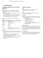
The Fidas24 analyzer has always at least 1 sample component
with 2 measuring ranges.
Up to 4 sample components with up to 2 measuring ranges are
possible for each measuring component.
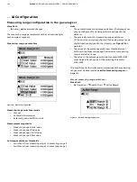
Setting measuring ranges
The measuring ranges are factory-set per customer order.
The measuring range can be varied as follows depending on the
adjusted amplification:
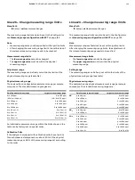
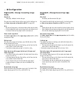
• Small amplification: from 10000 ppm C1 to 100 ppm C1
• Large amplification:: from 3000 ppm C1 to 10 ppm C1
The smallest measuring range is 0 to 5 mg org. C/m
3
corresponding to 0 to 10 ppm CH
4
.
Note
The associated amplification levels are set at the factory during
calibration. They can only be changed using the
Optima TCT Light test and calibration software.
Test gases
Test Gases for Zero Calibration
Quality
Nitrogen, Quality 5.0, synthetic air or catalytically
cleaned air with an organic C < 1 % MBU
Inlet pressure p
e
1000 hPa, ±100 hPa
Flow rate
130 to 250 l/h
Test gases for endpoint calibration
Quality
Sample component or substitute gas component
in nitrogen or synthetic air with concentration
adjusted to the measuring range
Inlet pressure p
e
1000 hPa, ±100 hPa
Flow rate
130 to 250 l/h
Zero point offset
If the zero point gas is not completely free of hydrocarbons
(even purified nitrogen contains fractions of hydrocarbons),
negative measured values may be displayed in small measuring
ranges.
In this case, the sample gas contains a lower proportion of
hydrocarbons than the zero point gas.
Test gas supply
The test gases for the zero and span calibration must be fed in
via solenoid valves; the test gases are connected automatically
by means of the integral valves.
If the test gas is connected at the sample gas inlet the zero gas
and span inlet gas must be sealed.
Test gas flow monitoring (pressure switch)
Test gas pressure and Test gas flow
If the test gas pressure is set in such a way that the test gas flow
at the sample gas inlet complies with the gas inlet conditions
(130 to 250 l/h), then the test gas surplus flows in the direction
of the gas sampling point and thus prevents sample gas
fractions from falsifying the calibration result.
If the test gas is fed directly at the sample gas inlet, see
on page 87, it must also be supplied in
depressurized state with an excess (130 to 250 l/h).
Test gas flow monitoring during automatic
calibration
(pressure switch)
If the test gases are connected at the separate test gas inlets,
the built-in pressure switch can be activated during automatic
calibration to monitor the flow of the test gases.
If the flow is insufficient, calibration is stopped.
The pressure switch can be activated for
• Zero point gas
• end-point gas and
• zero point and end-point gas
.
The activation of the pressure switch is configured using the
ECT software tool in the ‘Automatic Calibration’ dialog.


