EL3000
CONTINUOUS GAS ANALYZERS | OI/EL3000-EN REV. D
149
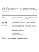
Active component selection
Menu Path
‘
Operation /
Switch-Over /
Active Component’
Figure 80: Menu ‘Active Component’
Active component
The ‘Active Component’parameter appears in the Magnos206,
Magnos28 and Caldos27 analyzer.
Several sample components can be calibrated for these
analyzers. However, there is always only one component
measured and displayed.
Magnos206, Magnos28
For Magnos206 and Magnos28, the measured components are
factory-configured. In the ‘Active Component’ menu, select a
measured component to be measured and displayed.
Caldos27
Selection of the active measured component is done in two
steps:
1. In the configurator, up to four sample components can be
selected from the context menu of the Caldos27 detector,
which are then loaded into the gas analyzer.
The factory-configured ‘Standard Gas’ component cannot
be deleted. It is also not possible to delete a ‘user
component’ which was factory-configured in the analyzer.
2. In the ‘Active Component’ menu of the gas analyzer,
select a sample component to be measured and
displayed from the maximum five sample components.
Calibration
All measured components are pre-calibrated at the factory. After
the initial activation of a sample component, zero point and end
point must be checked and recalibrated if necessary.
Externally controlled measured component
switch
Description
The externally controlled switch of the active sample component
is possible via appropriately configured digital inputs (see
on page 97). Appropriately configured digital
outputs are required for the sample component feedback.
Functionality
The sample component is activated via a signal at the digital
input assigned to the sample component switchover. The
correspondingly configured digital output is set for the
feedback of the active sample component.
If there is no signal at any of the configured digital inputs upon
restart of the gas analyzer, the last sample component stored as
active becomes active again.
Configuration using ECT
Figure 81: Menu ‘IO Connections’
In the example shown in the figure, the following digital inputs
and outputs are assigned to the Caldos27 detector (see yellow
marking):
• Digital inputs X24-DI2 to X24-DI4 for external control of
the sample component switchover (‘Comp. Control’) and
• The digital outputs X24-DO2 to X24-DO4 for the sample
component feedback (‘Comp. Feedback’).

