18
EAS822, EBS852, EBS862
ELECTRONIC UNIT | OI/EAS822/EBS852/EBS862-EN REV. D
… 6 Electrical connections
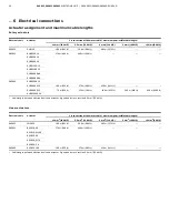
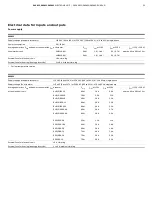
… Conductor cross-section on electronic
unit
EBS852 – Clamping connection
Suited for cable Ø Terminals for conductor
cross-section
Mains cable
13 mm (0.51 in)
max. 4 mm
2
(12 AWG)
Signal cable (DCS)
8 mm (0.31 in)
max. 1.5 mm
2
(16 AWG)
Transmitter (option)
8 mm (0.31 in)
max. 1.5 mm
2
(16 AWG)
Motor cable
13 mm (0.51 in)
max. 4 mm
2
(12 AWG)
Sensor cable
8 mm (0.31 in)
max. 1.5 mm
2
(16 AWG)
EBS852 – Terminal area for strain relief Ø
Motor/brake
13 mm (0.51 in)
Mains
13 mm (0.51 in)
Signals
8 mm (0.31 in)
EBS862 – Clamping connection
Terminals for conductor cross-section
Mains cable
max. 6 mm
2
(10 AWG)
Signal cable (DCS)
max. 4 mm
2
(12 AWG)
Transmitter (option)
max. 4 mm
2
(12 AWG)
Motor cable
max. 6 mm
2
(10 AWG)
Sensor cable
max. 4 mm
2
(12 AWG)
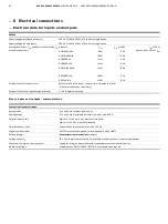
Conductor cross-section on universal plug
Crimp pins
Motor / brake / heater
max. 1.5 mm
2
(16 AWG)
Signals
max. 0.5 mm
2
(20 AWG)
Contact surface
Gold-plated
Screw terminals (optional)
Motor / brake / heater
max. 2.5 mm
2
(14 AWG)
Signals
max. 2.5 mm
2
(14 AWG)
Contact surface
Motor / brake / signals:
Gold-plated
Heater:
Silver-plated
Cable glands
The actuators and electronic units are supplied without cable
glands. Suited cable glands must be installed on site.
Tap holes for cable glands
metric
Power supply
M20 × 1.5 (1 ×)
Signal cable
M20 × 1.5 (3 ×)
Motor cable
M25 × 1.5 (1 ×)
Selection of suited connection cables
Please observe the following information when selecting cables:
• Use shielded cables for the motor/brake cable, the
sensor cable, and the signal cable to the control
system/controller.
• Connect the shielding of the motor/brake cable and the
sensor cable on both sides (to the actuator and to the
Contrac electronic unit).
Potential equalization
In order to avoid the risk of an electric shock, it must not be
possible to come into contact with dangerous live parts and
conductive parts that can be touched should not become
dangerous live parts either under standard conditions or under
conditions when a single fault occurs.
The actual current flowing in the event of a fault is obtained
from the phase to ground voltage and the total impedance
present in the fault circuit.
For long cables, the voltage drop may be dangerous to come
into contact with high current flowing.
Preferably, the electronic unit and the actuator must be
connected with low resistance (ground resistance < 0.1
Ω
) to the
potential equalization.
In the process, the respective standards of the VDE 100 series
must be observed.

