background image

26 

EAS822, EBS852, EBS862

 ELECTRONIC UNIT  |  OI/EAS822/EBS852/EBS862-EN REV. D 


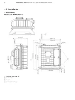
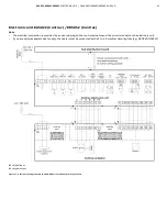
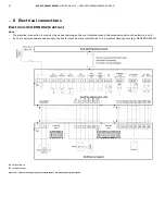
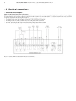
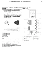
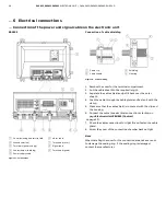
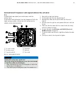
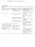
… 6  Electrical connections 

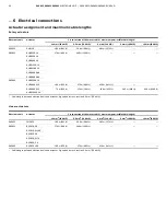
… Electrical data for inputs and outputs 
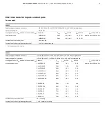
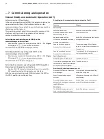
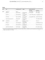
 

EBS862 

Supply voltage (standard actuators) 

230 V AC (190 to 260 V); 47.5 to 63 Hz; single-phase 

Supply voltage (Ex actuators) 

230 V AC (190 to 253 V); 47.5 to 63 Hz; single-phase 

Average power loss P

avg

 and power consumption I

max


of the electronic unit 


Actuator 

P

avg


l

max

 at 230 V 

l

pos

 (230 V):  

approx. 40 to 50 % of l

max


RHD(E)2500-10 

80 W 

5.3 A 

RHD(E)4000-10 

100 W 

10.0 A 

RHD8000-12 

115 W 

8.0 A 

RHDE8000-15 

115 W 

8.0 A 

RHD(E)16000-30 

115 W 

12.5 A 


RSD(E)50-10,0 

100 W 

6.4 A 

RSD100-10.0 

115 W 

12.5 A 

External fuse for electronic unit 

Safety fuse 35 A (Lindner) + thermal circuit breaker 16 A (ETA) 
(fuses are in the scope of delivery) 

External fuse for heating (dewing protection) 

2 to 6 A, medium time-lag 


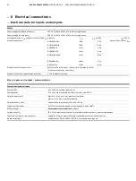
Binary inputs and outputs - communication 


Conventional communication 

Analog input 

0 / 4 to 20 mA, internal load: 300 

Ω


Analog output 

0 / 4 to 20 mA, electrically isolated, maximum load: 500 

Ω


3 digital inputs, 1 to 3 

Digital 

0: −3

 to 5 V or open, electrically isolated 

Digital 1: 12 to 35 V, electrically isolated 

3 digital outputs, 1 to 3 

Potential-free relay contact, max. 60 V, 150 mA 

Digital communication 

RS232 for commissioning and service, optionally FSK / HART® 

Default settings 

Conventional communication

 on page 11 

Voltage output U

V


24 V, 15 mA, electrically isolated, for scanning external contacts, or similar applications 

Connection for transmitter (optional) 

Supply for two-wire transmitter with activated process controller in Contrac 

Individual settings 

See data sheet ‘DS/CONTRAC/SETTING’ or available upon request. 


Change from one to two columns 


Summary of Contents for EBS862

Page 1: ...n the actuator and the control system During continuous positioning the electronic unit varies the motor torque continuously until the actuator force and the control valve force are balanced High response sensitivity and high positioning accuracy with short positioning time ensure an excellent control quality and a long actuator life Additional Information Additional documentation on EAS822 EBS852...

Page 2: ...cross section on electronic unit 17 Conductor cross section on universal plug 18 Cable glands 18 Selection of suited connection cables 18 Potential equalization 18 Actuator assignment and maximum cable lengths 20 Electronic unit EAS822 Contrac EBS852 Contrac 21 Connection examples 23 Electrical data for inputs and outputs 25 Connection of the power and signal cable on the electronic unit 27 Connec...

Page 3: ...ons and repairs to the product may only be performed if expressly permitted by these instructions Information and symbols on the product must be observed These may not be removed and must be fully legible at all times The operating company must strictly observe the applicable national regulations relating to the installation function testing repair and maintenance of electrical products Warnings T...

Page 4: ...he product and your network or any other network as the case may be Operator shall establish and maintain any appropriate measures such as but not limited to the installation of firewalls application of authentication measures encryption of data installation of anti virus programs etc to protect the product the network its system and the interface against any kind of security breaches unauthorized...

Page 5: ...tion without cover for terminal compartment EBS862 1 Electronic unit cover 2 Lifting eye 3 Commissioning and service field 4 Cover screws 5 Cover hinges 6 Tap holes for cable entries 7 Ground terminal 8 Terminals power supply 9 Terminals motor cable 0 Binary output fuses k Terminals signals l Lower part of electronic unit Figure 2 Presentation without cover for terminal compartment The EBS862 elec...

Page 6: ...n a mounting rack or for integrated assembly smallest actuator type In addition to the terminals the electronic unit contains the microprocessor frequency converter for motor control analog and binary inputs and outputs PROFIBUS or HART communication interfaces the commissioning and service field and a plug connection to connect a PC No matter what the motor power of the respective actuator is all...

Page 7: ...EAS822 EBS852 EBS862 ELECTRONIC UNIT OI EAS822 EBS852 EBS862 EN REV D 7 Overview Figure 3 Structure of the Contrac components example ...

Page 8: ...he maximum cable length depends on the actuator type and cable cross section see Actuator assignment and maximum cable lengths on page 20 EBS852 IP rating IP 20 Humidity 75 annual average condensation not permitted Rack air inlet temperature 0 to 45 C 32 to 113 F Transport and storage temperature 25 to 70 C 13 to 158 F Long term storage temperature 25 to 40 C 13 to 104 F Mounting position vertical...

Page 9: ...l cable glands down Vibration stress 2 to 9 Hz maximum deflection 3 mm 0 12 in 9 to 200 Hz acceleration 1 g Paint 2 layer component epoxy RAL 9005 black Electrical connection Mains supply via screw terminals all other connections made via screw type plug connectors Maximum cable length electronic unit actuator 470 m at 10 mm2 1542 ft at 8 AWG Weight 40 kg 88 lbs The maximum cable length depends on...

Page 10: ...on Figure 5 Software name plate example Note In electronic units which can be separated for assembly the name plate for the hardware is located on the lower part of the electronic unit Figure 1 The name plate for the software Figure 2 and an additional name plate for the hardware Figure 3 are located on the electronic unit cover The lower part of the electronic unit and the electronic cover are in...

Page 11: ... after unpacking for possible damage that may have occurred from improper transport Details of any damage that has occurred in transit must be recorded on the transport documents All claims for damages must be submitted to the shipper without delay and before installation Transporting the device Safety instructions DANGER Danger to life due to falling or toppling loads Risk of death or serious inj...

Page 12: ...ic areas that may be accessed by unauthorized persons the operator is required to take suited protective measures EAS822 EBS852 1 Fasten the electronic unit to the vertical mounting rail of the mounting rack using grade 8 8 screws Tensile strength 800 N mm2 116032 pounds square in yield strength 640 N mm2 92826 pounds square in 2 Provide adequate room for installation and ensure easy access 3 The ...

Page 13: ...ic units in a mounting rack on site we recommend laying the cables in accordance with the following illustrations Front view Side view Top view 1 Electronic units 2 Thermally conductive plates 3 Mains distribution 4 Cable guiding Figure 7 Installing the electronic unit and guiding the cable in the mounting rack example Change from two to one column ...

Page 14: ...14 EAS822 EBS852 EBS862 ELECTRONIC UNIT OI EAS822 EBS852 EBS862 EN REV D 5 Installation Dimensions Electronic unit EAS822 Contrac Figure 8 Dimensions in mm in ...

Page 15: ...EAS822 EBS852 EBS862 ELECTRONIC UNIT OI EAS822 EBS852 EBS862 EN REV D 15 Electronic unit EBS852 Contrac Figure 9 Dimensions in mm in ...

Page 16: ...ECTRONIC UNIT OI EAS822 EBS852 EBS862 EN REV D 5 Installation Dimensions Electronic unit EBS862 Contrac 1 Front section open rotated 90 2 Rotational radius 3 Tap holes Figure 10 Dimensions in mm in Change from one to two columns ...

Page 17: ...re dangerous if touched or implement additional isolation measures for them Each actuator requires a suited Contrac electronic unit with installed actuator specific software Observe the information in the operating instruction The specifications on the name plates of the electronic unit and actuator must match to guarantee correct hardware and software allocation Instructions on the use of Error C...

Page 18: ...and electronic units are supplied without cable glands Suited cable glands must be installed on site Tap holes for cable glands metric Power supply M20 1 5 1 Signal cable M20 1 5 3 Motor cable M25 1 5 1 Selection of suited connection cables Please observe the following information when selecting cables Use shielded cables for the motor brake cable the sensor cable and the signal cable to the contr...

Page 19: ... small conductor cross section of the motor cable e g 1 5 mm2 the maximum permissible cable length can be increased The ground resistance of the potential equalization conductor must be 0 1 Ω The maximum permissible shutdown time of 200 ms in case of a fault is complied with in the process Max cable length Conductor cross section EBS852 EBS862 4 mm2 12 AWG 460 m 1509ft 127 m 416 ft 6 mm2 10 AWG 46...

Page 20: ...S862 RHDE2500 10 RHDE4000 10 160 m 525 ft 270 m 886 ft 430 m 1411 ft RHDE8000 15 70 m 230 ft 120 m 394 ft 190 m 623 ft 280 m 919 ft 460 m 1509 ft RHDE16000 30 Cable length between electronic unit and actuator Signal cable cross section 0 5 mm 20 AWG Linear actuators Electronic unit Actuator Cross section of the motor cable maximum permissible cable length 1 5 mm2 16 AWG 2 5 mm2 14 AWG 4 mm2 12 AWG...

Page 21: ...n is provided by a universal plug on the control actuator and the screw terminals on the electronic unit If you are using a separate heat supply the heater must be protected with a 2 to 6 A medium time lag fuse e g NEOZED D01 E14 BE digital input BA digital output Figure 11 Control via analog input 0 4 to 20 mA HART communication or digital inputs ...

Page 22: ...ection is provided by a universal plug on the control actuator and the screw terminals on the electronic unit If you are using a separate heat supply the heater must be protected with a 2 to 6 A medium time lag fuse e g NEOZED D01 E14 BE digital input BA digital output Figure 12 Control via analog input 0 4 to 20 mA HART communication or digital inputs ...

Page 23: ...he binary inputs are configured as MANUAL OPERATION To switch the actuator to automatic mode AUT the following conditions must be met The binary input 1 must be connected with 24 V DC automatic operation The AUT operating mode must be selected through the graphic user interface Figure 13 Connection example for operation following a continuous set point standard configuration ...

Page 24: ...ses instead of an analog setpoint The following conditions must be fulfilled in order to implement the step controller pulses The binary inputs must be configured using the STEP CONTROLLER function The binary input 1 must be connected with 24 V DC automatic operation The AUT operating mode must be selected through the graphic user interface Figure 14 Connection example for operation downstream fro...

Page 25: ... standard actuators 115 V AC 94 to 130 V or 230 V AC 190 to 260 V 47 5 to 63 Hz single phase Supply voltage Ex actuators 115 V AC 94 to 127 V or 230 V AC 190 to 253 V 47 5 to 63 Hz single phase Average power loss Pavg and power consumption Imax of the electronic unit Actuator Pavg lmax at 115 V lmax at 230 V lpos 115 V 230 V approx 40 to 50 of lmax RHD E 250 10 60 W 1 8 A 0 9 A RHD E 500 10 75 W 2...

Page 26: ...in the scope of delivery External fuse for heating dewing protection 2 to 6 A medium time lag Binary inputs and outputs communication Conventional communication Analog input 0 4 to 20 mA internal load 300 Ω Analog output 0 4 to 20 mA electrically isolated maximum load 500 Ω 3 digital inputs 1 to 3 Digital 0 3 to 5 V or open electrically isolated Digital 1 12 to 35 V electrically isolated 3 digital...

Page 27: ...2 Contrac on page 21 External fuses for EBS862 1 External safety fuse 35 A 2 External safety fuse 16 A 3 Electronic unit Figure 15 External fuses Note The conductor cross section between the fuses and the electronic unit must be at least 2 5 mm2 AWG 14 In addition to the internal fuses the EBS862 electronic unit requires two additional external fuses which are supplied separately with the assembly...

Page 28: ...emove the cover for the terminal compartment 2 Cut the cable sheath to the required length 3 Separate the cable shield and pull it back over the outer sheath 4 Push the cable through the cable gland and fasten it with the clamp 5 Make sure that the cable shield is in contact with the clip and the housing 6 Connect the cable see electrical connections starting on page Electronic Unit EBN862 Contrac...

Page 29: ...tion When connecting the shielding make sure that the individual wires of the cables are not damaged When installing the connector housing make sure that the sealing ring is not damaged If the sealing ring is damaged contact the manufacturer 1 Remove the connector housing 2 Cut the cable sheath to the required length 3 Separate the cable shield and pull it back over the outer sheath 4 Push the cab...

Page 30: ...on Engineering Software ECOM688 and ECOM700 Using the ECOM688 ECOM700 engineering software the user can read out store and write back the actuator related data from the electronic unit of a Contrac control actuator Depending on the software version of the electronic unit two different engineering software versions are available Contrac electronic units with software version 2 00 require ECOM700 Co...

Page 31: ...the adjustment process LED 100 0 Depending on the flash rate this LED indicates the adjustment process position saved MAN operating mode manual via commissioning and service field from software version 2 00 or higher or an error Reset button Press to restart the processor If the adjustment is not yet terminated the set end positions are deleted Operating element Description Write protection switch...

Page 32: ...st either LED 100 flashes at 1 Hz and LED 0 continues to flash at 4 Hz or vice versa Accept 2 Position correct Both LEDs flash at 1 Hz Failure Both LEDs flash alternately at 4 Hz ECOM688 or ECOM700 mode Both LEDs light continuously from software version 2 00 MAN operating mode manual through ISF The LED 0 flashes at 1 Hz LED 100 is off from software version 2 00 MAN Manual operating mode via binar...

Page 33: ...uccessful the corresponding LED flashes at a rate of 1 Hz The other LED will continue to flash at approx 4 Hz Defining the second position 0 or 100 4 Use one of the travel buttons to move to the second position 5 To accept the position press the Accept button If successful both LEDs will flash at a rate of approx 1 Hz Saving the settings 6 Press both Accept buttons to accept the settings The LEDs ...

Page 34: ...ed the LED for the 100 position is continually lit up Signaling on the commissioning and service field Function Display Device setup Switch to Device setup Press and hold down both travel buttons for approx 5 s After this time both LEDs will then flash in sync at 4 Hz Approach an end position Move to the desired end position by pressing the travel button Both LEDs will continue to flash at 4 Hz du...

Page 35: ...he actuator is switched off and the actuator functions are no longer available Previous error messages are stored in the Saved Errors area in the electronic unit Use the graphic user interface to read out saved errors Error messages cannot be reset until the cause of the error has been eliminated Alarm Diagram Set point monitoring Transmitter monitoring Maintenance Actuator temperature Temperature...

Page 36: ...are monitoring Standstill Min speed Movement in incorrect direction Frequency converter end positions Error position transmitter memory Flash Error RAM error Watchdog monitoring activated Monitoring ON Error signal Error message via actual value ON Saved errors reset option Analog output 1 to 3 5 mA with low alarm 21 5 to 25 mA with high alarm Interference display ON ...

Page 37: ...ts on the electronic unit are not wired Make connection Brake does not release no mechanical click Check the brake air gap approx 0 25 mm 0 010 in and electrical connection to the brake Check winding resistance of the brake coil Actuator does not run in automatic mode although automatic mode is selected in the user interface Digital input 1 BE 1 not wired Make connection Check the software setting...

Page 38: ...es the remaining operating time until the next routine maintenance is required Use the configuration program to view this information 10Repair Repair and maintenance activities may only be performed by authorized customer service personnel When replacing or repairing individual components use original spare parts Returning devices Use the original packaging or a secure transport container of an ap...

Page 39: ...ast acting 10 A super fast acting Fuse for binary outputs 3x Connection area G fuse cartridge 5 20 mm 0 2 A medium time lag EBS862 External fuse External Safety fuse thermal circuit breaker 35 A 16 A Brake fuse Power supply board G fuse cartridge 5 20 mm 0 315 A medium time lag DC link fuse Power supply board G fuse cartridge 6 3 32 mm 15 A super fast acting Fuse for binary outputs 3x Connection a...

Page 40: ...ccordance with WEEE Directive 2012 19 EU If there is no possibility to dispose of the old equipment properly our Service can take care of its pick up and disposal for a fee Notice on RoHS II Directive 2011 65 EU As of 7 22 2019 the products provided by ABB Automation Products GmbH fall within the scope of regulations on hazardous substances with restricted uses or the directive on waste electrical...

Page 41: ...dress Contact person Telephone Fax Email Device details Type Serial no Reason for the return description of the defect Was this device used in conjunction with substances which pose a threat or risk to health Yes No If yes which type of contamination please place an X next to the applicable items biological corrosive irritating combustible highly extremely combustible toxic explosive other toxic s...

Page 42: ...42 EAS822 EBS852 EBS862 ELECTRONIC UNIT OI EAS822 EBS852 EBS862 EN REV D Trademarks HART is a registered trademark of FieldComm Group Austin Texas USA ...

Page 43: ...EAS822 EBS852 EBS862 ELECTRONIC UNIT OI EAS822 EBS852 EBS862 EN REV D 43 Notes ...

Page 44: ...ent without prior notice With regard to purchase orders the agreed particulars shall prevail ABB does not accept any responsibility whatsoever for potential errors or possible lack of information in this document We reserve all rights in this document and in the subject matter and illustrations contained therein Any reproduction disclosure to third parties or utilization of its contents in whole o...

Reviews: