4-4 Electrical Installation and Planning
MN448
4.3.1 Fuse / Circuit Breaker Selection
Suitable fuses to provide wiring protection of the input power cable should be installed in the incoming supply line,
according to the data in Table 4-2 Electrical Ratings. The fuses must comply with any local codes or regulations in place. In
general, type gG (IEC 60269) or UL type J fuses are suitable; however, in some cases type aR fuses may be required.
Check that the operating time of the fuse is below 0.5 seconds. The operating time depends on the fuse type, the supply
network impedance as well as the cross sectional area, material and length of the supply cable. In case the 0.5 seconds
operating time is exceeded with gG fuses, ultra-rapid (aR) fuses in most cases reduce the operating time to an acceptable
level.
Where allowed by local regulations, suitably dimensioned type B MCB circuit breakers of equivalent rating may be utilized in
place of fuses, providing that the clearing capacity is sufficient for the installation.
The maximum permissible short circuit current at the drive input power terminals as defined in IEC60439-1 is 5kA.
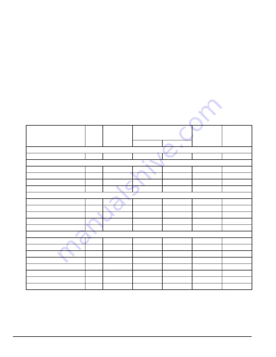
Table 4-2 Fuse & Wire Size Electrical Specifications
The rated fuse currents given in the table are the maximums for the mentioned fuse types. If smaller fuse ratings are use,
check that the fuse rms current rating is larger than the rated input amps shown in the rating tables in Chapter 2.
Drive Type
Top (T) / Axial (A)
Power
(HP)
Nominal Input
Current (A)
Fuse UL (Class J)
or MCB (Type B)
Maximum
Cable Size
(AWG) 1
Nominal
Output
Current
Non UL
UL
2,3,4
1-phase 100V…115V AC (+/-10%) - 3 Phase 230V Output
ECS100T/A 1H1DF4
1
15.1
25
20
14
3.2
1-phase 200…240V AC (+/-10%) - 3 Phase 230V Output
ECS100T/A 8H1DF4
1
12.9
16
17.5
14
7.0
ECS100T/A 8H2DF4
2
12.9
16
17.5
14
7.0
ECS100T/A 8H3DF4
3
12.9
16
17.5
12
7.0
ECS100T/A 8H3EF4
3
12.9
16
17.5
12
7.0
3-phase 200…240V AC (+/-10%) - 3 Phase 230V Output
ECS100T/A 2H1DF4
1
7.5
10
10
14
4.3
ECS100T/A 2H2EF4
2
7.5
10
10
14
4.3
ECS100T/A 2H3DF4
3
12.9
16
17.5
14
7.0
ECS100T/A 2H3EF4
3
12.9
16
17.5
14
7.0
ECS100T/A 2H5EF4
5
10.5
16
15
10
10.5
3-phase 380…480V AC (+/-10%) - 3 Phase 460V Output
ECS100T/A 4H1DF4
1
3.5
6
6
14
2.2
ECS100T/A 4H2DF4
2
3.5
10
10
14
2.2
ECS100T/A 4H3DF4
3
5.6
10
10
14
4.1
ECS100T/A 4H3EF4
3
5.6
10
10
14
4.1
ECS100T/A 4H5EF4
5
7.5
10
10
14
5.8
ECS100T/A 4H7EF4
7.5
11.5
16
15
12
9.5
ECS100T/A 4H7FF4
7.5
12
16
15
12
12.0
ECS100T4H10FF4
10
12
16
15
10
12.0
1. Cable sizes shown are the maximum possible that may be connected to the drive. Cables should be selected according
to local wiring codes or regulations applicable at the point of installation.
2. Refer to the UL Online Certification Directory for a list of UL Recognized products, File Number E226333.
3. The integral overload protection does not provide branch circuit protection. Branch circuit protection must be provided in
accordance with applicable local regulations and the National Electrical Code.
4. Fuse type: UL JDDZ Class J.
5. Where permitted, equivalent circuit breakers may be used.
Summary of Contents for EC Titanium Series
Page 1: ... MN448_May 2020 May 2020 EC Titanium Manual User s guide ...
Page 10: ...1 4 Introduction MN448 ...
Page 20: ...3 4 Mechanical Information and Mounting MN448 ...
Page 26: ...4 6 Electrical Installation and Planning MN448 ...
Page 32: ...5 6 Control Pad Wiring and Keypad Interface MN448 ...
Page 36: ...6 4 Keypad Programming and Basic Operation MN448 ...
Page 44: ...8 4 Parameter Navigation and Groups MN448 ...
Page 51: ...9 7 Control Modes MN448 ...
Page 77: ...11 8 Standalone Motor and ABB Drive Setup MN448 ...
Page 99: ...A 12 Modbus RTU Example Connection MN448 ...
Page 102: ......


