3.6 Setting the Configuration
Chapter 3: Configuration
168
493-0736-11 (6-2)
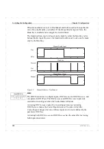
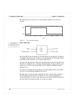
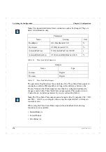
The Pulse output is active for 30 seconds and then inactive for 20 (50–30)
seconds.
Figure 56
Two State Pulse Example.
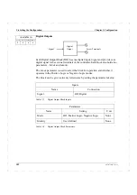
Three State Pulse
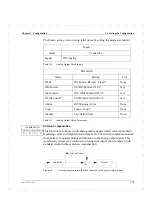
The Three State Pulse output has two analog inputs,
FeedbackSignal
and
Signal
,
two digital outputs,
Increase
and
Decrease
. It also holds three analog parameters,
DeadBand, ActuatorPosTime,
and
ActuatorMinPulseLen.
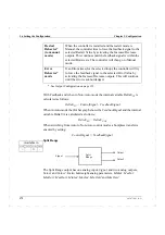
As long as the input signal (which is the output from the control block) increases,
the
Increase
output is active. As long as the input signal decreases, the
Decrease
output is active. When the input signal is stable within the deadband, neither
output is active.
To connect the output
Increase
and
Decrease
pulse signals to the system under
control, two of the Digital Outputs must be used.
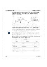
The parameter
ActuatorPosTime
represents the time it takes for the actuator to
travel its entire span (from 0.0% to 100.0%, or vice versa). The parameter
ActuatorMinPulseLen
(value in percent) represents a buffer threshold (a value in
percent) used for determining when to activate any output.
Time
False
True
–10
0
10
20
30
40
50
60
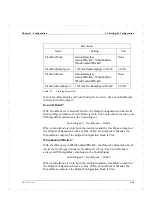
Available in
ECA06
ECA60
ECA600 EMA60
-
X
X
-
Signal
Feedback Signal
Three
State
Pulse
Increase
Decrease
Summary of Contents for ECA06
Page 1: ...Version 1 05 ECA06 60 600 EMA60 Configuration and Installation ...
Page 2: ......
Page 3: ...ECA06 60 600 EMA60 Configuration and Installation ...
Page 10: ...Contents vi 493 0736 11 6 2 ...
Page 16: ...1 5 Version information Chapter 1 Introduction 16 493 0736 11 6 2 ...
Page 200: ...4 2 Annual Check Chapter 4 Maintenance 200 493 0736 11 6 2 ...
Page 286: ...Appendix A Configuration Work Sheets 282 493 0736 11 6 2 ...
Page 304: ...B 1 Total Reset Appendix B Special Modes 298 493 0736 11 6 2 ...
Page 308: ...Index 302 493 0736 11 6 2 ...
Page 309: ......

