Chapter 2: Installation
2.2 Installation with Cassette
493-0736-11 (6-2)
19
2.2
Installation with Cassette
External Dimensions
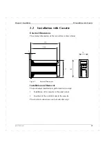
The external dimensions of the controller are shown below
Figure 2
External Dimensions.
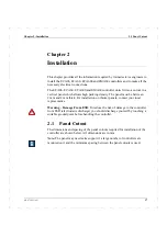
Installation and Removal
The mechanical installation is performed in two steps:
1
Installation of the cassette in the panel cutout.
2
Insertion of the controller unit in the cassette.
The electrical connections can be made after step 1.
72
144
200
235
11
137
Summary of Contents for ECA06
Page 1: ...Version 1 05 ECA06 60 600 EMA60 Configuration and Installation ...
Page 2: ......
Page 3: ...ECA06 60 600 EMA60 Configuration and Installation ...
Page 10: ...Contents vi 493 0736 11 6 2 ...
Page 16: ...1 5 Version information Chapter 1 Introduction 16 493 0736 11 6 2 ...
Page 200: ...4 2 Annual Check Chapter 4 Maintenance 200 493 0736 11 6 2 ...
Page 286: ...Appendix A Configuration Work Sheets 282 493 0736 11 6 2 ...
Page 304: ...B 1 Total Reset Appendix B Special Modes 298 493 0736 11 6 2 ...
Page 308: ...Index 302 493 0736 11 6 2 ...
Page 309: ......

