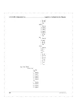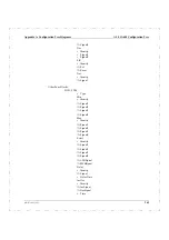
Appendix A: Configuration Tree Diagrams
493-0736-11 (6-2)
249
Appendix A
Configuration Tree Diagrams
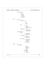
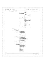
The following pages show the Configuration menu tree structures for each of the
controllers: ECA06, ECA60, ECA600 and EMA60.
The different tabulation levels indicate the different levels in the configuration
tree. This means that all items on the same tabulation level are on the same tree
level.
Items preceded by a bullet (
•
item) are parameters.
Items preceded by a right double-arrow (
⇒
item) are inputs.
A term in square brackets, e.g. FA1[AddSub Value], means the value of the output
from the block FA1 which is of the type AddSub.
Note:
Outputs are not available to the user for configuration. When making a
connection between an input and an output, the input is configured to point to an
output.
Summary of Contents for ECA06
Page 1: ...Version 1 05 ECA06 60 600 EMA60 Configuration and Installation ...
Page 2: ......
Page 3: ...ECA06 60 600 EMA60 Configuration and Installation ...
Page 10: ...Contents vi 493 0736 11 6 2 ...
Page 16: ...1 5 Version information Chapter 1 Introduction 16 493 0736 11 6 2 ...
Page 200: ...4 2 Annual Check Chapter 4 Maintenance 200 493 0736 11 6 2 ...
Page 286: ...Appendix A Configuration Work Sheets 282 493 0736 11 6 2 ...
Page 304: ...B 1 Total Reset Appendix B Special Modes 298 493 0736 11 6 2 ...
Page 308: ...Index 302 493 0736 11 6 2 ...
Page 309: ......

