Chapter 2: Installation
2.4 Electrical Installation
493-0736-11 (6-2)
25
2.4
Electrical Installation
Warning – Fuses:
To prevent the risk of fire or injury to personnel in the event of
a short-circuit the a.c. mains supply must be fitted with a 6 A slow blow fuse. No
more than five units should be connected to the same supply. If more controllers
are required then each set of five should be connected to a separate, fused mains
supply.
General
The electrical installation is performed in four steps:
1
Configuring the jumper module.
2
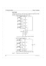
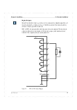
Signal connections.
3
Connection of data communications link (if applicable).
4
Connection of the power supply cabling.
Installation of the controller in an electrically noisy environment is described at
the end of this section. The electrical connections can be made either before or
after the cassette is mounted in the panel. The terminal blocks at the rear of the
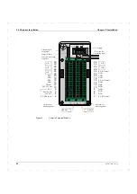
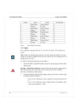
cassette are shown in Figure 9.
Summary of Contents for ECA06
Page 1: ...Version 1 05 ECA06 60 600 EMA60 Configuration and Installation ...
Page 2: ......
Page 3: ...ECA06 60 600 EMA60 Configuration and Installation ...
Page 10: ...Contents vi 493 0736 11 6 2 ...
Page 16: ...1 5 Version information Chapter 1 Introduction 16 493 0736 11 6 2 ...
Page 200: ...4 2 Annual Check Chapter 4 Maintenance 200 493 0736 11 6 2 ...
Page 286: ...Appendix A Configuration Work Sheets 282 493 0736 11 6 2 ...
Page 304: ...B 1 Total Reset Appendix B Special Modes 298 493 0736 11 6 2 ...
Page 308: ...Index 302 493 0736 11 6 2 ...
Page 309: ......

