Chapter 2: Installation
2.4 Electrical Installation
493-0736-11 (6-2)
31
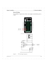
Supply ground to ground terminal.
Supply neutral to terminal 4.
Supply live to terminal 1.
Note:
The ground connection must always be connected to ground when the
controller is connected to the mains supply.
When an AC supply is used a +24 V supply is available from terminals Z10
(+24 V) and Z2 (0 V) to supply external units, e.g. transmitters. The maximum
loading on these terminals is 150 mA.
D.C. Supply
The controller can operate from a +24 V DC power supply, maximum power
consumption 15 W.
Notes:
• The supply terminals at the rear of the cassette can accommodate wire of
maximum size 1.5 mm
2
.
• It is strongly recommended that the d.c. supply should be fused appropriately.
To connect the d.c. supply proceed as follows:
1
Switch the d.c. supply Off and disconnect the d.c. supply cable from the d.c.
outlet.
2
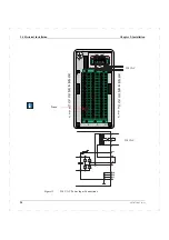
Connect the cable to the supply terminals at the rear of the cassette as
follows:
Supply positive to terminal Z6.
Supply negative to terminal Z4.
Note:
Remove the jumper between Z8 and Z6.
I/O Signal Wiring
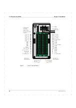
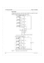
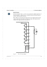
All the input and output signals are connected to the terminal block. The
maximum wire size which can be connected to the terminal block is 1.5 mm
2
.
Summary of Contents for ECA06
Page 1: ...Version 1 05 ECA06 60 600 EMA60 Configuration and Installation ...
Page 2: ......
Page 3: ...ECA06 60 600 EMA60 Configuration and Installation ...
Page 10: ...Contents vi 493 0736 11 6 2 ...
Page 16: ...1 5 Version information Chapter 1 Introduction 16 493 0736 11 6 2 ...
Page 200: ...4 2 Annual Check Chapter 4 Maintenance 200 493 0736 11 6 2 ...
Page 286: ...Appendix A Configuration Work Sheets 282 493 0736 11 6 2 ...
Page 304: ...B 1 Total Reset Appendix B Special Modes 298 493 0736 11 6 2 ...
Page 308: ...Index 302 493 0736 11 6 2 ...
Page 309: ......

