2.4 Electrical Installation
Chapter 2: Installation
34
493-0736-11 (6-2)
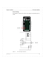
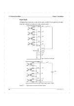
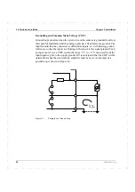
Figure 16
Three-wire connection with 24 V supply from the controller.
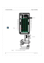
Figure 17
Separately supplied sensor with output signal electrically isolated from ground.
If an actuator potentiometer is used with a three-state pulse output it should be
connected as shown in Figure 18. In this case the potentiometer is fed from AO2.
The voltage type input has a fixed reference.
Transmitter
signal
–
+
J2
J1
250
Ω
AI1
+
–
z32
z10
z2
d16
d24
z30
d2
supply
+
+24 V
Transmitter
signal
–
+
J2
J1
250
Ω
AI1
+
–
z32
z30
z2
d16
d24
d2
supply
EXT
Summary of Contents for ECA06
Page 1: ...Version 1 05 ECA06 60 600 EMA60 Configuration and Installation ...
Page 2: ......
Page 3: ...ECA06 60 600 EMA60 Configuration and Installation ...
Page 10: ...Contents vi 493 0736 11 6 2 ...
Page 16: ...1 5 Version information Chapter 1 Introduction 16 493 0736 11 6 2 ...
Page 200: ...4 2 Annual Check Chapter 4 Maintenance 200 493 0736 11 6 2 ...
Page 286: ...Appendix A Configuration Work Sheets 282 493 0736 11 6 2 ...
Page 304: ...B 1 Total Reset Appendix B Special Modes 298 493 0736 11 6 2 ...
Page 308: ...Index 302 493 0736 11 6 2 ...
Page 309: ......


