Chapter 2: Installation
2.4 Electrical Installation
493-0736-11 (6-2)
41
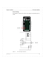
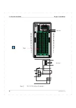
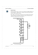
Figure 25
Example of Single Controller Current Loop.
Sensor 4–20 mA
5 V
5 V
5 V
5 V
28 V
CMV referenced
to this point
20 mA
48V DC
+
–
AI
250
Ω
250
Ω
250
Ω
250
Ω
+
–
+
–
+
–
+
–
+
–
Supply Unit
Meter
Controller
Indicator 1
Indicator 2
1
6
2
3
4
5
Summary of Contents for ECA06
Page 1: ...Version 1 05 ECA06 60 600 EMA60 Configuration and Installation ...
Page 2: ......
Page 3: ...ECA06 60 600 EMA60 Configuration and Installation ...
Page 10: ...Contents vi 493 0736 11 6 2 ...
Page 16: ...1 5 Version information Chapter 1 Introduction 16 493 0736 11 6 2 ...
Page 200: ...4 2 Annual Check Chapter 4 Maintenance 200 493 0736 11 6 2 ...
Page 286: ...Appendix A Configuration Work Sheets 282 493 0736 11 6 2 ...
Page 304: ...B 1 Total Reset Appendix B Special Modes 298 493 0736 11 6 2 ...
Page 308: ...Index 302 493 0736 11 6 2 ...
Page 309: ......

