background image

3.6 Setting the Configuration

Chapter 3: Configuration

76


493-0736-11 (6-2)

Table 19

AddSub Outputs.

Note:


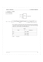
The AddSub block in the ECA06 does not have the input Signal3 or the 

parameter Factor3 and hence the function is defined as:

Value = Factor1 

×


S Factor2 

×

 S Bias

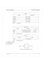
MulDiv

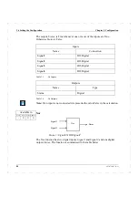
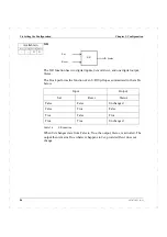
The MulDiv function has four analog inputs, 

Signal1

Signal2

Signal3

 and 

Signal4

, and one analog output, 

Value

. The block holds two parameters; a gain 

Factor

, and 

Bias

Note:


If any input is unconnected, it represents the value 1.0.

Outputs

Name

Type

Value

Analog 

Available in

ECA06

ECA60

ECA600 EMA60

-

X

X

X

Signal1

Signal2

Signal3

Signal4

MulDiv

Value

Value

Factor

Signal1 Signal2

×

Signal3 Signal4

×

-----------------------------------------------

×

Bias

+

=

Summary of Contents for ECA06

Page 1: ...Version 1 05 ECA06 60 600 EMA60 Configuration and Installation ...

Page 2: ......

Page 3: ...ECA06 60 600 EMA60 Configuration and Installation ...

Page 4: ... notice and do not constitute any binding undertakings from ABB Automation Technology Products AB ABB Automation Technology Products AB is not responsible under any circumstances for direct indirect unexpected damage or consequent damage that is caused by this document All rights reserved Release 0230 Document version 6 2 Document number 493 0736 11 Printed in Sweden ...

Page 5: ...n with Cassette 19 External Dimensions 19 Installation and Removal 19 2 3 Installation with Mounting Plates and IP65 Gasket 23 2 4 Electrical Installation 25 General 25 Power Wiring 27 I O Signal Wiring 31 Communications signal wiring RS485 38 Communications signal wiring RS232 38 Connections in an Electrically Noisy Environment 38 3 Configuration 43 3 1 Configuring the Process Value 43 Configurat...

Page 6: ...Connections 60 Overview 62 Input Function Blocks 74 Arithmetic Function Blocks 74 Logic Function Blocks 82 Other Functions 88 Set Point Block 116 Alarms 132 Control 136 Output Configuration 155 Output Functions 166 Outputs 176 ECA Operator Block 184 EMA60 Operator Block 190 System Block 193 3 7 Status Signals 198 3 8 Test Mode 198 4 Maintenance 199 4 1 General 199 4 2 Annual Check 199 5 Technical ...

Page 7: ...ith Feed Forward and Gain Scheduling 210 Description 210 Mechanical Installation 210 Definition of Control Problem 210 Preset Configurations 211 Selection of I O 211 Electrical Installation 212 Configuration 214 Startup 219 A 2 Temperature Control and Communication with COMLI 220 Description 220 Definition of the Control Problem 220 Mechanical Installation 221 Preset Configurations 221 Selection o...

Page 8: ...rithmetic Error 243 CLPM Osc LoopX 243 XX Source off 243 Tuner Abort LoopX 243 Tuner PVNoise LoopX 243 Adapt Warn LoopX 243 B 5 Information Messages 243 Alarm Messages 243 Tuning 243 B 6 Summary of Messages 244 System Error Error and Warning Messages 245 Information Messages 247 C Configuration Tree Diagrams 249 C 1 ECA06 Configuration Tree 250 C 2 ECA60 Configuration Tree 254 C 3 ECA600 Configura...

Page 9: ...ion 289 E 3 Communication Facilities 292 Changing Communication Mode 294 Changing Control Modes 294 Changing Loops 295 E 4 Front Panel Usage 295 E 5 Communication Area Mapping 295 I O RAM Map 295 Register Map 297 Writing K 300 Writing TI and TD 301 F Special Modes 303 F 1 Total Reset 303 Index 305 ...

Page 10: ...Contents vi 493 0736 11 6 2 ...

Page 11: ...scribes all the configurable options available for each controller Chapter 4 Maintenance contains maintenance instructions to ensure the continued safe operation of the controllers Chapter 5 Technical Data contains a summary of the features of the controllers Appendix A Application Examples contains detailed configuration instructions for some typical applications Appendix B Error Warning and Info...

Page 12: ...tion Symbols Warning and information symbols appear in the left margin adjacent to paragraphs containing important information The symbols should be interpreted as follows A warning sign denotes a danger of injury to personnel or that caution is required to avoid damage to the equipment A sign for mandatory action denotes steps necessary to bring the equipment into operation but without immediate ...

Page 13: ...to environmental conditions exceeding the values stated in the technical data in the Configuration and Installation Manual The ECA controllers should not be used in an environment where there is a risk of exposure to strong electrical interference Always follow precautions for handling electrostatic sensitive devices when handling the ECA controllers 1 5 Version information Version 1 00 The first ...

Page 14: ...iteEnable enables writing via COMLI in Communication Mode Local The parameter ESPLock is added to the Set Point Block which means that the controller can be locked in ESP mode The RestartBehaviour parameter is supplemented with new modes The IncDec Block has improved functions Two input signals for tracking and two parameters for output signal limitation are added Version 1 05 Changes and addition...

Page 15: ...e now writeable from a supervisory system via communication Support for the communication protocol MODBUS RTU has been added A Stiction Compensation function has been added to the analog outputs Three decimals are now available in the arithmetic blocks Start Abort Tuning and Alarm acknowledge are now possible from a supervisory system via communication ...

Page 16: ...1 5 Version information Chapter 1 Introduction 16 493 0736 11 6 2 ...

Page 17: ... must be between 2 mm and 4 mm thick For installation on thicker panels contact your local representative Warning Damage From ESD To reduce the risk of damage to the controller from ESD electrostatic discharge you should discharge yourself by touching a suitable ground point before handling the controller 2 1 Panel Cutout The dimensions and spacing of the panel cutouts required for installation of...

Page 18: ...2 1 Panel Cutout Chapter 2 Installation 18 493 0736 11 6 2 Figure 1 Panel Cutouts Min 180 138 1 Min 76 67 1 ...

Page 19: ...rnal dimensions of the controller are shown below Figure 2 External Dimensions Installation and Removal The mechanical installation is performed in two steps 1 Installation of the cassette in the panel cutout 2 Insertion of the controller unit in the cassette The electrical connections can be made after step 1 72 144 200 235 11 137 ...

Page 20: ...6 11 6 2 Figure 3 Cassette and Springs Installation of the Cassette 1 Push the empty cassette into the panel cutout and let it hang down by its own weight with the upper edge pressing against the upper edge of the cutout Figure 4 Empty Cassette Hanging in the Cutout ...

Page 21: ... 2 for the upper retaining spring Figure 5 Mounting the Retaining Springs Removing the Cassette Removal is the reverse of installation Proceed as follows 1 Press the front part of the lower retaining spring back If the mounting panel is thick it may be necessary to use a screwdriver to do this 2 Lever the retaining spring out 3 Repeat steps 1 and 2 for the upper retaining spring 4 Withdraw the cas...

Page 22: ...distinct click Take care not to press on the LCD display window or the push buttons 3 Check the mounting force by trying to pull out the controller by hand Removing the Controller Unit To remove the controller unit from the cassette proceed as follows 1 Place the tip of a broad screwdriver 6 8 mm into the small opening on the upper or lower part of the front frame as shown in Figure 6 2 Gently twi...

Page 23: ... To install the controller with the mounting plates and IP65 gasket proceed as follows 1 Remove the two mounting plates from the controller unit by removing the four fixing nuts at the rear of the controller 2 If you require IP65 sealing mount the IP65 gasket by rolling it forward from the rear of the controller to the front frame Check that the gasket is correctly installed in groove at the front...

Page 24: ...s and IP65 Gasket Chapter 2 Installation 24 493 0736 11 6 2 Removal Removal is the reverse of installation Note To ensure IP65 sealing the IP65 gasket must be exchanged for a new one if the unit is reinstalled Figure 8 Mounting the Gasket ...

Page 25: ... each set of five should be connected to a separate fused mains supply General The electrical installation is performed in four steps 1 Configuring the jumper module 2 Signal connections 3 Connection of data communications link if applicable 4 Connection of the power supply cabling Installation of the controller in an electrically noisy environment is described at the end of this section The elect...

Page 26: ... 22 20 18 16 14 12 10 8 6 4 z b d Ground shield connection Jumper module Pin screw for mount ing plates DI1 DI2 DI3 DI4 DI com 24 V DC out 24 V 24 V DC in 24 V DC 0 V RS com AI1 AI3 AI5 Tx Rx RS485 Tx Rx RS232 0 V AI com AO1 AO2 AO3 0 V AO com DO6 DO5 DO4 DO3 DO2 DO1 0 V DO com AI4 AI2 Pin screw for mounting plates Pin screw for mounting plates Pin screw for mounting plates AC supply 1 10 ...

Page 27: ...ontroller can operate from a direct current supply or an alternating current supply Figure 10 D C Power Supply Connections 115VAC L N 230VAC TA L N 2 32 30 28 26 24 22 20 18 16 14 12 10 8 6 4 2 32 30 28 26 24 22 20 18 16 14 12 10 8 6 4 z b d 24V DC 19V AC 19V AC 24V DC Z6 Z4 d24 d16 d2 z2 ...

Page 28: ...llation 28 493 0736 11 6 2 Figure 11 230 V AC Power Input Connections 115VAC L N 230VAC TA L N 2 32 30 28 26 24 22 20 18 16 14 12 10 8 6 4 2 32 30 28 26 24 22 20 18 16 14 12 10 8 6 4 z b d 1 2 3 4 z10 z6 z8 z4 d24 d16 d2 z2 230 VAC 230 VAC Note ...

Page 29: ...llation 493 0736 11 6 2 29 Figure 12 115 V AC Power Input Connections 115VAC L N 230VAC TA L N 2 32 30 28 26 24 22 20 18 16 14 12 10 8 6 4 2 32 30 28 26 24 22 20 18 16 14 12 10 8 6 4 z b d 1 2 3 4 z10 z8 z6 z4 d24 d16 d2 z2 115 VAC Note 115 VAC ...

Page 30: ...Shock Hazard Always ensure that the mains supply cable is disconnected from the mains outlet before connecting it to the controller otherwise a lethal shock hazard exists 2 Connect jumpers and cable to the supply terminals at the rear of the cassette as follows see also Figure 9 For 230 VAC operation connect a jumper between terminals 2 and 3 For 115 VAC operation connect jumpers between terminals...

Page 31: ...DC power supply maximum power consumption 15 W Notes The supply terminals at the rear of the cassette can accommodate wire of maximum size 1 5 mm2 It is strongly recommended that the d c supply should be fused appropriately To connect the d c supply proceed as follows 1 Switch the d c supply Off and disconnect the d c supply cable from the d c outlet 2 Connect the cable to the supply terminals at ...

Page 32: ...ound using lug connectors Connection to the chassis ground is available at the four screws at the rear panel Figures 14 to 17 give examples of how to connect different types of analog input to the controller Note For voltage input the appropriate jumper must be removed Figure 13 I O Signal Wiring J1 J2 z32 AI1 AI2 AI3 AI4 AI5 z30 d32 d30 z28 z26 d28 d26 z24 z22 d24 signal ground d16 d2 z2 J3 J4 J5...

Page 33: ...4 Two wire connection with 24 v supply from the controller Figure 15 Separately supplied sensor with output signal electrically connected to ground Transmitter signal J2 J1 250 Ω AI1 z32 z30 z2 d16 d24 z10 d2 Transmitter signal J2 J1 250 Ω AI1 z32 z30 z2 d16 d24 z10 d2 supply EXT ...

Page 34: ... signal electrically isolated from ground If an actuator potentiometer is used with a three state pulse output it should be connected as shown in Figure 18 In this case the potentiometer is fed from AO2 The voltage type input has a fixed reference Transmitter signal J2 J1 250 Ω AI1 z32 z10 z2 d16 d24 z30 d2 supply 24 V Transmitter signal J2 J1 250 Ω AI1 z32 z30 z2 d16 d24 d2 supply EXT ...

Page 35: ...If an analog output is not used the output terminals should be short circuited otherwise there is a risk of initiating an error message for open circuit output Figure 19 AO1 used AO2 and AO3 not used J8 J7 AO2 d20 d28 z2 d16 d24 d26 d2 signal ground AI4 AO2 d20 d22 z2 d16 d24 d18 d2 signal ground AO3 AO1 ...

Page 36: ...pto couplers The supply may be taken from the controller or from an external current source Figure 20 Digital Input Internal and External Supplies Digital Input External Supply DI1 z20 DI2 z18 DI3 z16 DI COM z12 DI4 z14 24V Digital Input Internal Supply DI2 DI3 DI4 DI COM z20 z18 z16 z14 z12 24V z10 d16 d2 z2 d24 signal ground DI1 ...

Page 37: ...ode such as a 1N4003 or similar The diode should be wired as close as possible to the coil DO1 to DO6 are open emitter current source transistor outputs The maximum current is limited to a maximum of 250 mA per output total maximum load 500mA The outputs are short circuit protected Figure 21 DO1 to DO6 Internal Supply DO1 24V d4 d16 d2 z2 d24 signal ground DO2 d6 DO3 d8 DO4 d10 DO5 d12 DO6 d14 ...

Page 38: ...tabilizer should be installed This type of equipment can of course be used to supply a number of controllers however you must ensure that no electrically noisy equipment is connected to the secondary side the same side as the controller Follow the manufacturer s recommendations concerning grounding of this type of transformer Screening The input and output wiring to field mounted equipment e g sen...

Page 39: ...cal Installation 493 0736 11 6 2 39 Figure 22 Screening Connections Figure 23 Controller Connections in an Enclosure with an Intermediate Terminal Block Wrong Right Ground Rail analog signals digital signals z b 2 3 4 2 3 4 z b 1 power ...

Page 40: ...nputs should then be connected as differential inputs i e with floating ground references so that the inputs are floating with respect to the signal ground Such an input can receive a CMV within the range 5 V to 17 V measured from the input negative pole to the supply ground If it is anticipated that the CMV will be outside this range then an isolation amplifier must be used An example of a ground...

Page 41: ...ation 493 0736 11 6 2 41 Figure 25 Example of Single Controller Current Loop Sensor 4 20 mA 5 V 5 V 5 V 5 V 28 V CMV referenced to this point 20 mA 48V DC AI 250 Ω 250 Ω 250 Ω 250 Ω Supply Unit Meter Controller Indicator 1 Indicator 2 1 6 2 3 4 5 ...

Page 42: ...unded at one single point so that it does not float away from ground and introduce a large interference potential Table 2 shows the potential at points 1 to 6 with respect to ground and indicates which points are suitable for grounding Table 2 Grounding Points Point Potential Grounding Possibility 1 10 V Not permitted max CMV 0V 2 5 V Not permitted max CMV 0V 3 0 V Permitted 4 5 V Permitted 5 10 V...

Page 43: ...e in the Configuration Mode and includes full instructions for the configuration of the controllers When configurating the regulator must be in Manual mode ECA600 both loops in order to change the parameters In this mode neither the operator nor the controller can change the output signal 3 1 Configuring the Process Value One of the first things any user will want to do is configure the Process Va...

Page 44: ... four parameters you can configure NumberOfDecimals defines the number of decimal places displayed for the Process Value e g setting NumberOfDecimals to 3 will give a displayed Process Value in the form 1 234 MinValue and MaxValue define the lower and upper limits respectively of the acceptable range for the Process Value Unit defines the engineering unit in which the Process Value is shown and ap...

Page 45: ... OK key 6 Repeatedly press the Up or Down key until you reach the Operator Block 7 Press the OK key to enter the Operator Block Note If the unit is an ECA600 the following is displayed Press the OK key to proceed Config 600 001 05 00 Enter Code 6845 Cancel OK Config 600 001 05 00 Code correct Full access Return OK Config 600 001 05 00 Operator Return OK Operator PID1 Return OK ...

Page 46: ...ameter 11 Press the Up or Down key to scroll through the values 0 4 displayed on the third line of the display 12 When the number of decimal places shown is 2 press the OK key 13 Press the Up or Down key until the second line of the display shows MinValue 14 Press the OK key 15 Press the Up or Down key to scroll through the range of values allowed for MinValue PID1 Process Value Return OK Process ...

Page 47: ...ll through the range of values allowed for MaxValue 20 When the required MaxValue 120 is displayed press the OK key 21 Press the Up or Down key until the second line of the display shows Unit 22 Press the OK key 23 Press the Up or Down key to scroll through the range of units allowed 24 When the required Unit C is displayed press the OK key Process Value MinValue 20 Cancel OK Process Value MaxValu...

Page 48: ...1 Configuring the Process Value Chapter 3 Configuration 48 493 0736 11 6 2 25 The Configuration is complete Repeatedly press the Cancel key until you return to Operator Mode Process Value Unit C Cancel OK ...

Page 49: ...Configuration Mode the functions of certain controls on the front panel are different from in Operator Mode The controls and indicators are described below Figure 26 Controls and Indicators Cancel Key Display Next Key Up Key Auto Manual Key OK Key Output Process Value Setpoint Down Key Indication Manual ...

Page 50: ... changes as the Up Down keys are pressed When the parameter is at the required value press the OK key to store the value The third line is then blank again The bottom line describes the present functions of the Cancel OK and Next keys Each key function is labelled in inverse text above the key If the key has no function at this particular level of the Configuration tree the space above it on the d...

Page 51: ...l Control Keys In the Configuration Mode the function of the OK Cancel and Next keys depends on the present position in the menu structure By pressing these keys and the Up and Down keys you can navigate the Configuration tree structure to enable and define all the parameters needed for Configuration OK Key Press the OK key green tick to descend to the next level in the tree structure or to save a...

Page 52: ...the Next key is shown on the bottom line of the display Up Key Press the Up key to step up through a list of options for the currently selected parameter or to move to the previous parameter in the current branch of the tree Down Key Press the Down key to step down through a list of options on the display or to move to the next parameter in the current branch of the tree Hand Key The Hand key is n...

Page 53: ...roller enters the Configuration mode the display shows the following Figure 29 Configuration Mode Start up Display Where XXX Software type 06 for ECA06 60 for ECA60 600 for ECA600 and MI for EMA60 ZZZ ZZ ZZ Software Version e g 001 05 00 Password Configured To enter Configuration Mode if a password has been configured 1 Press and hold the Next key 2 You are prompted to enter the password This is a...

Page 54: ... not enter the correct password you have read only access Figure 33 Read Only Access to Configuration Mode 6 In either case press the OK key and you are free to navigate the Configuration tree structure using the keys as described below 7 If you have restricted access pressing the Up Down keys to change the parameter has no effect and the OK soft key label does not appear Config 600 001 05 00 Ente...

Page 55: ...the correct password you can retrieve it as follows 1 When the display shows Code NOT Correct Read access only press the Next key and hold it for a few seconds Figure 34 Accessing the Crypt Key 2 The Crypt Key FFFE in the above example is shown on the display This is an encoded version of the password shown in hexadecimal format 3 To retrieve the password first convert the Crypt Key to decimal for...

Page 56: ...nfigure the parameter You can connect the inputs of some blocks to the outputs of others to create more complex functions Application examples are given in Appendix A Navigating the Configuration Menu Navigation through the Configuration Menus contained in Appendix C is via the following simple steps 1 Access the Configuration Menu as described in section 3 3 2 To move down one level in the menu o...

Page 57: ...s described in section 3 3 2 Press the Up or Down key until the second line of the display shows Outputs 3 Press the OK key 4 Press the Up or Down key until the second line of the display shows Analog Outputs 5 Press the OK key 6 Press the Up or Down key until the second line of the display shows AO1 7 Press the OK key 8 Press the Up or Down key until the second line of the display shows Mode Conf...

Page 58: ...e available in each controller For example FAx represents any of the numbered Arithmetic Function Blocks The specific number of blocks in each type of controller is given in a table in the left hand margin next to the block being described Some types of function blocks are available in a limited number An example is the delay block in the ECA600 where only two instances are available If you try to...

Page 59: ...nput DIC Digital Input Communication Buffer DU Digital User Input Function FA Arithmetic Function FL Logic Function FO Other Function Set Point SP Set Point Alarm AA Absolute Alarm DA Deviation Alarm Control CO Control OC Output Configuration Output Function OF Output Function Output AO Analog Output AOC Analog Output Communication DO Digital Output DOC Digital Output Communications Operator OP Op...

Page 60: ...onnections Free Connections Fixed Connections are preset at the factory and are not changeable by the user The Fixed Connections are shown with thick lines on the Configuration Work Sheet Appendix D The Free Connections may have default settings from the factory but the user can always change them Making Connections When connecting inputs and outputs the inputs are always assigned an output In the...

Page 61: ...on has been made between an output of block A and an input of block B Then suppose block A is switched OFF Now this B input is connected to an output whose value is undefined In this situation when block B is executed and the input above requests a value from the A output the controller will continue to execute and the following will happen 1 The A output signals to the error handling system that ...

Page 62: ...locks There are three types Arithmetic Function Blocks FA Logic Function Blocks FL and Other Function Blocks FO The Other Function Blocks have inputs and outputs that are both analog and digital The Set Point column contains Set Points The Alarm column contains Absolute alarms and Deviation alarms The Control column contains Control and Output Configuration blocks which carry out control and relat...

Page 63: ...ing Columns The inputs and outputs are not shown Refer to Configuration Work Sheets on page 277 The EMA60 does not have a Control block AI Inputs Input Functions Set Point Control Output Functions Outputs AIC AU DI DIC DU CO OC OF AO DO AOC DOC OP SY FA FL FO SP AA DA Alarms Operator System ...

Page 64: ...scaling and calculation is done within the block The output Value is in the range 0 0 to 1 0 which corresponds to 0 to 100 of the input Each block also holds the parameters Mode RootExtraction FilterTime Alarm Loop and Identity Note The Loop parameter is only available on the ECA600 Table 4 Analog Input Block Parameters Parameters Name Setting Unit Mode Off 0 20 mA 4 20 mA 0 5 V 1 5 V 0 10 V 2 10V...

Page 65: ...t the parameter Mode to Off By setting the Root Extraction parameter to On the characteristic of the signal on the terminals is changed according to the graph shown below Figure 36 Root Extraction Characteristic Example This function is useful in flow applications where differential pressure is measured to obtain the flow Outputs Name Type Value Analog Terminal Input Value Terminal input Value 100...

Page 66: ... Error Warning and Information Messages If a warning is set the controller displays a message while continuing to operate normally The parameter Loop is used only on the ECA600 Alarms can be set to act on either loop independently The control block designated by the Loop parameter for alarm will react according to the parameter ErrorBehavior in the Control block The other Control block loop will c...

Page 67: ...ock also holds two parameters Table 6 Analog Input Communications Buffer Parameters Table 7 Analog Input Communications Buffer Outputs To select an analog input for use configure the parameter Mode to on To deselect an analog input set the parameter Mode to Off Each block may be given a twenty letter identification name by configuring the parameter Identity Each buffer corresponds to one unique re...

Page 68: ... to Ratio or Bias Values while the controller is in operation Each block produces one analog output signal Value Each block also holds seven parameters Table 8 Analog User Block Parameters Parameters Name Setting Unit Mode Off On None NumberOfDecimals 0 NumberOfDecimals 4 None LoLimit 99999 LoLimit 99999 None HiLimit 99999 HiLimit 99999 None Identity User defined text None MinValue 100 0 MinValue ...

Page 69: ...se decrease i e NumberOfDecimals 1 step 0 1 NumberOfDecimals 2 step 0 01 Each user defined input must lie within a specified range Configure the parameters LoLimit and HiLimit to set this range The output of this type of block is always in the range 100 0 to 100 0 Lolimit always represents the value 1 0 100 and HiLimit the value 1 0 100 Each block may be given a twenty letter identification name b...

Page 70: ...Value Value MaxValue The default values of MinValue 0 0 and MaxValue 100 0 define the default signal range 100 0 Value 100 By adjusting MinValue and MaxValue the user can limit the signal range to positive values only MinValue 0 0 or any other permissible range The Displayed Range is the range of the value presented on the display This range is LoLimit Displayed Value HiLimit MaxValue MinValue Dis...

Page 71: ...value displayed for MinValue and HiLimit determines the value displayed for MaxValue Digital Inputs Digital Input Blocks DI can accept one digital input signal and produce one digital output signal Status Each block also holds two parameters Table 10 Digital Input Block Parameters Table 11 Digital Input Block Outputs To select a digital input for use set the parameter Mode to the required logic mo...

Page 72: ...bit To configure a Digital Communications Buffer for use set the parameter Mode to on To deselect a digital buffer set the parameter Mode to Off Each block may be given a twenty letter identification name by configuring the parameter Identity Each buffer corresponds to one unique I O bit Note See Appendix E for a full list of I O bits and their addresses Table 12 Digital Input Communications Buffe...

Page 73: ...ext True is shown on the display Each block can accept one digital input and produces one digital output signal Status Each block also holds two parameters Mode and Identity Table 14 Digital User Block Parameters Table 15 Digital User Block Outputs To enable a Digital User Block set the parameter Mode to on To disable the block set Mode to Off Each block may be given a twenty letter identification...

Page 74: ...lock provided that they are of the same type i e analog to analog or digital to digital Each output may be connected to several inputs if required The Arithmetic Function Blocks FA can be interconnected to allow more complex functions to be constructed from basic operators The available arithmetic function blocks are summarised in Table 16 Table 16 Arithmetic Function Blocks To configure an Arithm...

Page 75: ...Factor2 and Factor3 and one bias value Bias The Value output is equal to the sum of the three gain adjusted inputs added to the bias Table 17 AddSub Inputs Table 18 AddSub Parameters Inputs Name Connection Signal1 Off Analog Signal2 Off Analog Signal3 Off Analog Parameters Name Setting Unit Factor1 10 00 Factor1 10 00 None Factor2 10 00 Factor2 10 00 None Factor3 10 00 Factor3 10 00 None Bias 10 0...

Page 76: ...actor1 Signal1 Factor2 Signal2 Bias MulDiv The MulDiv function has four analog inputs Signal1 Signal2 Signal3 and Signal4 and one analog output Value The block holds two parameters a gain Factor and Bias Note If any input is unconnected it represents the value 1 0 Outputs Name Type Value Analog Available in ECA06 ECA60 ECA600 EMA60 X X X Signal1 Signal2 Signal3 Signal4 MulDiv Value Value Factor Si...

Page 77: ...lDiv Block Outputs Exp Value Factor SignalPower Bias Inputs Name Connection Signal1 Off Analog Signal2 Off Analog Signal3 Off Analog Signal4 Off Analog Parameters Name Setting Unit Factor 10 00 Factor 10 00 None Bias 10 00 Bias 10 00 None Outputs Name Type Value Analog signal Available in ECA06 ECA60 ECA600 EMA60 X X Signal Exp Value ...

Page 78: ... exponential Power a gain Factor and a Bias Table 23 Exp Inputs Table 24 Exp Parameters Table 25 Exp Outputs Note If the input is not connected it represents the value 0 0 Bias in the calculation Inputs Name Connection Signal Off Analog Parameters Name Setting Unit Power 0 00 Power 10 00 None Factor 10 00 Factor 10 00 None Bias 10 00 Bias 10 00 None Outputs Name Type Value Analog signal ...

Page 79: ...on The block has three analog inputs Pdiff Pabs and T and one analog output Value It also holds seven analog parameters Table 26 Comp Inputs Inputs Name Connection Pdiff Off Analog Pabs Off Analog T Off Analog Available in ECA06 ECA60 ECA600 EMA60 X X Pdiff Pabs T Comp Value Value Factor Pdiff Pabs PabsMax PabsMin PabsMin Porifice Torifice 273 T Tmax Tmin Tmin 273 ...

Page 80: ...quired set Pabs Off Parameters Name Setting Unit Factor 10 0 K 10 0 none PabsMax 0 0 PabsMax 10000 0 see note PabsMin 0 0 PabsMin 10000 0 see note Porifice 0 0 Porifice 10000 0 see note Torifice 273 0 Torifice 10000 0 C Tmax 273 0 Tmax 10000 0 C Tmin 273 0 Tmin 10000 0 C Outputs Name Type Value Analog signal Value Factor Pdiff Pabs PabsMax PabsMin PabsMin Porifice Value Factor Pdiff Torifice 273 T...

Page 81: ...l Set to Off if no absolute pressure compensation is required PabsMax Constant see note Pressure sensor upper measuring range limit absolute pressure PabsMin Constant see note Pressure sensor lower measuring range limit absolute pressure Porifice Constant see note Orifice plate design pressure Torifice Constant C Orifice plate design temperature T Analog input None Temperature signal linearised fr...

Page 82: ... complex logic functions to be constructed from basic operators For example connecting a digital function block set to NOT to the output of a block that is set to AND will give the logical NAND function And Status Signal1 AND Signal2 AND Signal3 AND Signal4 The And function has four digital inputs Signal1 Signal2 Signal3 Signal4 and one digital output Status Parameters Name Setting Unit Type Off A...

Page 83: ...nected it represents the value True in the calculation Or Status Signal1 OR Signal2 OR Signal3 OR Signal4 The Or block has four digital inputs Signal1 Signal2 Signal3 and Signal4 and one digital output Status Inputs Name Connection Signal1 Off Digital Signal2 Off Digital Signal3 Off Digital Signal4 Off Digital Outputs Name Type Status Digital Available in ECA06 ECA60 ECA600 EMA60 X X X Signal1 Sig...

Page 84: ... connected it represents the value False in the calculation Xor Status Signal1 XOR Signal2 The Xor function has two digital inputs Signal1 and Signal2 and one digital output Status The function is summarised in the table below Inputs Name Connection Signal1 Off Digital Signal2 Off Digital Signal3 Off Digital Signal4 Off Digital Outputs Name Type Status Digital Available in ECA06 ECA60 ECA600 EMA60...

Page 85: ...Inputs Table 37 Xor Outputs Note If an input is not connected it represents the value False in the calculation Inputs Output Signal1 Signal2 Status False False False False True True True False True True True False Inputs Name Connection Signal1 Off Digital Signal2 Off Digital Outputs Name Type Status Digital ...

Page 86: ... an S R flip flop as summarised in the table below Table 38 S R Function When Set changes state from False to True the output Status is activated The output then remains True whatever happens to Set provided Reset does not change Input Output Set Reset Status False False Unchanged False True False True False True True True Unchanged Available in ECA06 ECA60 ECA600 EMA60 X X Set Reset Status S R ...

Page 87: ... 39 S R Inputs Table 40 S R Outputs Note If an input is not connected it represents the value False in the calculation Not Status NOT Signal The Not function has one digital inputs Signal and one digital output Status The output Status is True whenever Signal is False and False when Signal is True Inputs Name Connection Set Off Digital Reset Off Digital Outputs Name Type Status Digital Available i...

Page 88: ...log input signals Their outputs to the control system are also mixed analog and digital signals The configuration options for the mixed function blocks are summarised below Table 43 Mixed Function Options Inputs Name Connection Signal Off Digital Outputs Name Type Status Digital Parameters Name Setting Unit Type Off Min Max Select Level Detector Delay IncDec Linear Rate Limiter Integrator Time Mea...

Page 89: ...alue and copies this value to the output Value The input selected by the block can be read from LSBStatus and MSBStatus Examples are given in the table below Table 44 Min Operation Note If two inputs have the same value LSBStatus and MSBStatus indicate the input with the smallest ordinal number Selected Input MSBStatus LSBStatus Signal1 False False Signal2 False True Signal3 True False Signal4 Tru...

Page 90: ...ry number that identifies the input with the smallest value The Signal1 input is denoted 0 zero Signal2 is denoted 1 one Signal3 is denoted 2 two and Signal 4 is denoted 3 three Inputs Name Connection Signal1 Off Analog Signal2 Off Analog Signal3 Off Analog Signal4 Off Analog Outputs Name Type Value Analog signal LSBStatus Digital MSBStatus Digital Signal1 Signal2 Signal3 Signal4 Value MSBStatus L...

Page 91: ...SBStatus This function selects the input with the largest value and copies this value to the output Value The input selected by the block can be read from LSBStatus and MSBStatus Examples are given in the table below Table 48 Max Operation Selected Input MSBStatus LSBStatus Signal1 False False Signal2 False True Signal3 True False Signal4 True True Available in ECA06 ECA60 ECA600 EMA60 X X X Signa...

Page 92: ...mple Table 51 Max Example MSBStatus and LSBStatus form a binary number that identifies the input with the greatest value The Signal1 input is denoted 0 zero Signal2 is denoted 1 one Signal3 is denoted 2 two and Signal 4 is denoted 3 three Inputs Name Connection Signal1 Off Analog Signal2 Off Analog Signal3 Off Analog Signal4 Off Analog Outputs Name Type Out Analog signal LSBStatus Digital MSBStatu...

Page 93: ... Select The Select function has four analog inputs Signal1 Signal2 Signal3 Signal4 and two digital inputs LSB and MSB The single analog output is the same as the selected input Available in ECA06 ECA60 ECA600 EMA60 X X X Signal1 Signal2 Signal3 Signal4 LSB MSB Select Value ...

Page 94: ...t When using four inputs both the LSB input and the MSB input are used to make the selection The function is summarised in the table below Table 52 Select Function Table 53 Select Inputs Table 54 Select Outputs MSB LSB Value False False Signal1 False True Signal2 True False Signal3 True True Signal4 Inputs Name Connection Signal1 Off Analog Signal2 Off Analog Signal3 Off Analog Signal4 Off Analog ...

Page 95: ...emains True until Signal becomes less than Lo and then it becomes False Status remains False until Signal becomes greater than Hi again and then it becomes True If LoLimitSignal Off then LoLimitValue is used for Lo otherwise LoLimitSignal is used If HiLimitSignal Off then HiLimitValue is used for Hi otherwise HiLimitSignal is used In short if the input is connected the value of the input is used o...

Page 96: ...3 6 Setting the Configuration Chapter 3 Configuration 96 493 0736 11 6 2 Figure 39 Level Detector Function Time Time Status Output Signal Input 90 100 80 70 60 50 40 30 20 10 0 ...

Page 97: ...ter DelayTime The input Signal is transferred to the output Value with a delay of DelayTime seconds DelayTime can be set to a maximum value of DelayTimeMax seconds Inputs Name Connection Signal Off Analog LoLimitSignal Off Analog HiLimitSignal Off Analog Parameters Name Setting Unit LoLimitValue 0 0 LoLimitValue HiLimitValue 100 0 None HiLimitValue 0 0 LoLimitValue HiLimitValue 100 0 None Outputs ...

Page 98: ... IncSignal and DecSignal and one analog output Value It also holds one analog parameter Time The analog output of this block can be controlled by the digital inputs The parameter Time specifies how long it takes for the output Value to change by 100 Inputs Name Connection Signal Off Analog Parameters Name Setting Unit DelayTime 0 DelayTime DelayTimeMax seconds Outputs Name Type Value Analog Availa...

Page 99: ...he IncSignal and the DecSignal inputs When activating DecSignal Value will not decrease below LoLimit and when activating IncSignal Value will not increase above HiLimit When TrackEnable is true the value of the TrackSignal input is copied to the Value output The IncSignal and DecSignal inputs are disregarded when TrackEnable is true The function of LoLimit and HiLimit always applies LoLimit Value...

Page 100: ...rameters Table 63 IncDec Outputs Inputs Name Connection IncSignal Off Digital DecSignal Off Digital TrackSignal Analog input TrackEnable Digital input Parameters Name Setting Unit Time 0 1 Time 1000 0 seconds 100 LoLimit 0 0 LoLimit HiLimit 100 0 HiLimit 0 0 LoLimit HiLimit 100 0 Outputs Name Type Value 0 Value 100 ...

Page 101: ...curate characterization Not all the breaking points have to be used Figure 40 Linear Function If In1 0 the leftmost end point and or In10 100 0 the rightmost end point the function will complete the characteristic so that all values of the input signal in the range 0 0 to 100 0 will have defined output values Available in ECA06 ECA60 ECA600 EMA60 X X X Signal Linear Value Value Output Signal Input...

Page 102: ...eristic would also be extended with a horizontal line Figure 41 Linear Example Note Only part of the graph is shown in the example above It is even possible to have step changes in the breaking points The output Value in the breaking point is defined by the coordinate with the ordinal number In the example below Value 10 0 for Signal 20 0 Signal Input Value Output 0 10 20 30 40 50 60 70 60 50 40 3...

Page 103: ...n automatic adjustment is made so that the successive entries are always greater than the preceding ones For example suppose In3 15 0 and In4 20 0 before you make any changes When you set In3 30 0 then automatically In4 30 0 Table 64 Linear Inputs Inputs Name Connection Signal Off Analog Value Output Signal Input 0 10 20 30 40 50 60 70 80 90 100 100 90 80 70 60 50 40 30 20 10 0 ...

Page 104: ... Out1 100 0 In2 In1 In2 100 0 Out2 0 0 Out2 100 0 In3 In2 In3 100 0 Out3 0 0 Out3 100 0 In4 In3 In4 100 0 Out4 0 0 Out4 100 0 In5 In4 In5 100 0 Out5 0 0 Out5 100 0 In6 In5 In6 100 0 Out6 0 0 Out6 100 0 In7 In6 In7 100 0 Out7 0 0 Out7 100 0 In8 In7 In8 100 0 Out8 0 0 Out8 100 0 In9 In8 In9 100 0 Out9 0 0 Out9 100 0 In10 In9 In10 100 0 Out10 0 0 Out10 100 0 ...

Page 105: ...The parameter Rate determines the limit If Signal has a rate of change faster then Rate then the output Value is in the form of ramp with slope Rate Table 67 Rate Limiter Inputs Table 68 Rate Limiter Parameters Outputs Name Type Value Analog Inputs Name Connection Signal Off Analog Parameters Name Setting Unit Rate 0 1 Rate 100 0 second Available in ECA06 ECA60 ECA600 EMA60 X X X Signal Rate Limit...

Page 106: ...tank there are gradations The space between any two gradations is fixed A flow from the inlet makes the water level rise and pass the gradation marks one after the other If instead the bottom outlet is opened the level will decrease and on its way down pass the gradation marks Each time the water level passes a gradation mark on its way up a pulse is generated Another pulse is generated when the t...

Page 107: ...lways equal to the parameter SampleTime Time and TimeUnit The parameter Time defines the period of time between two consecutive pulses at a Signal of 1 00 The parameter TimeUnit determines the unit of Time seconds or minutes The parameter Time corresponds to the radius of the tank The greater the radius the slower the water level will rise The permissible range of Time is as follows Timemin Time T...

Page 108: ...als DeadBand It is possible to make the block disregard Signals less than a user defined value by setting the parameter DeadBand The range of Signal is then restricted to DeadBand Signal 1 00 PositiveOnly By setting the parameter PositiveOnly to On the range is restricted to 0 0 Signal 1 00 IPC and Value remain unchanged as long as Signal is less than or equal to zero When Signal rises above zero ...

Page 109: ...et the block Activating the digital input ResetSignal has the same effect Resetting the block essentially means setting Value 0 00 and IPC 0 Reset empties the tank Hold has lower priority than Reset Table 70 Integrator Inputs Table 71 Integrator Parameters Inputs Name Connection Signal Analog input Hold Digital input ResetSignal Digital input Parameters Name Setting Unit TimeUnit seconds minutes T...

Page 110: ...3 6 Setting the Configuration Chapter 3 Configuration 110 493 0736 11 6 2 Table 72 Integrator Outputs Outputs Name Type Value Analog output Overflow Digital output Pulse Digital output ...

Page 111: ...es seconds The internal counter can be reset to zero by selecting Reset and pressing the OK key When the block is active and selected from the Operator Option List the time is shown on the controller display as below Figure 43 Time Measurement Display Table 73 Time Measurement Inputs Table 74 Time Measurement Parameters Inputs Name Connection Signal Off Digital Parameters Name Setting Unit Reset O...

Page 112: ... TimerRunning is 1 running if the timer function is running and is 0 not running if ActivateTimer is 0 not active or TimerDone is 1 active When the preset time has elapsed equal the parameter TimerTime then TimerDone is set to 1 and TimeRunning is reset to 0 When the block is active and selected from the Operator Option List the time is shown on the operator s display as below Figure 44 Timer Disp...

Page 113: ...onfiguration 493 0736 11 6 2 113 Table 76 Timer Parameters Table 77 Timer Outputs Parameters Name Setting Unit TimeUnit Seconds or Minutes TimerTime 3xSampleTime TimerTime 86400 Seconds Outputs Name Type TimerRunning Digital TimerDone Digital ...

Page 114: ...nfiguration menu The output CounterRunning is 1 running if the counter function is running and is 0 not running if ActivateCounter is 0 not active or CounterDone is 1 active CounterDone is set to 1 and CounterRunning is reset to 0 when the the preset number of pulses is reached When the block is active and selected from the Operator Option List the number of pulses counted is shown on the operator...

Page 115: ...er Inputs Table 79 Counter Parameters Table 80 Counter Outputs Inputs Name Connection ActivateCounter Off Digital CountSignal Off Digital ResetSignal Off Digital Parameters Name Setting Unit NbrOfPulses 1 NbrOfPulses 999 999 None Outputs Name Type CounterRunning Digital CounterDone Digital ...

Page 116: ...ains two Control blocks and therefore has two Set Point blocks The EMA60 Set Point block does not have an ESPEnable input an ESPSignal and associated parameters an ESPMode output or a Simple Set Point Ramp Available in ECA06 ECA60 ECA600 EMA60 X X X X PVSignal ESPSignal ESPEnable ECA Controllers Set Point PVValue SPValue RampDone RampActive ESPMode RampHold PVSignal EMA60 Set Point PVValue RampDon...

Page 117: ...r Table 81 Set Point Block Inputs Table 82 Set Point Block Parameters Inputs Name Connection PVSignal Off Analog ESPSignal Off Analog ESPEnable Off Digital Parameters Name Setting Unit SPLimitMode Off On None SPLoLimit MinValue SPLoLimit SPHiLimit MaxValue None SPHiLimit MinValue SPLoLimit SPHiLimit MaxValue None SP TrackMode Off TrackESP TrackPVInNonAuto None ESPLock Off On None ...

Page 118: ...ffer block AIC Set Point There are two different Set Points ISP Internal Set point set via the front panel ESP External Set Point block input The Set Point Block has two analog inputs PVSignal and ESPSignal and one digital input ESPEnable The block has two analog outputs PVValue and SPValue and four digital outputs RampDone RampActive ESPMode and RampHold Outputs Name Type PVValue 0 PVValue 100 SP...

Page 119: ... connected to this output the SP block will signal a warning on the display the External Set Point and ISP ESP entries are removed from the Operator Option List The object of the ESPLock parameter is to lock the controller in ESP mode Neither the operator nor the ESPEnable input must be able to switch into ISP mode When ESPLock is On the Set Point block permanently uses ESPSignal for Set Point The...

Page 120: ...the front panel Refer to the Operator s Manual section 4 5 ESPEnable and the front switch affect ESPMode as shown in the diagram below Figure 46 ISP ESP Switching SPValue The SPValue output from the block is the Set Point used by the Control block The Control Block has a fixed connection to the Set Point output but other blocks are also allowed to connect to this output SPLimitMode The parameter S...

Page 121: ...nt Tracking The internal set point can track another value by means of the parameter SPTrackMode There are two methods of tracking available If TrackESP is configured the value of the signal is copied to ISP TrackESP cannot be configured if ESPSignal is set to Off if it is set to Off after TrackESP has been configured the result is the same as if no tracking had been configured If the tracking is ...

Page 122: ...from False to True on the AutoStatus input start the Ramp function Manual Auto Forced Output Auto Tracking Auto The following Control Mode transitions which represent a change from True to False on the AutoStatus input stop the Ramp function Auto Manual Auto Forced Output Auto Tracking Parameters Name Setting Unit RampMode Off Simple Advanced None Hold Off On None TimeUnit Minutes Seconds None Ram...

Page 123: ...permanently connected to the controller Output Configuration Block via the digital signal AutoStatus When the controller Output Configuration Block is in Auto Control mode the Auto Status Output is active Note The parameter RampSpeed is entered in Engineering Units per TimeUnit This means that the setting of this parameter depends on the setting of the MinValue and MaxValue parameters in the Opera...

Page 124: ...onds or if TimeUnit Minutes The RampSpeed parameter uses the same number of decimals as defined by the parameter NumberOfDecimals in the Operator Block Example If MinValue 10 0 MaxValue 210 0 Unit C and TimeUnit Minutes then span 210 0 10 0 200 0 and The RampSpeed parameter in this example can be set between 0 14 RampSpeedMin and 12000 RampSpeedMax Unit second RampSpeedMin span 86400 Unit minute R...

Page 125: ... will then either start the ramp from the beginning Hold Off or make it continue from where it was interrupted Hold On The function of the RampHold output may be summarized RampHold Hold On OR ManualStatus OR NOT RampDone As long as the value of SPValue is changing the output RampActive is True while SPValue is constant RampActive is False The value of SPValue must be equal to the value of ISP ESP...

Page 126: ... t 1 the control Mode changes from non Auto Manual Tracking or Forced Output to Auto and the ramp starts In the example above with TimerTime 2 The time 5 minus 4 TimerTime and therefore the ramp is not complete Time SPValue AutoStatus Input RampActive Output RampDone Internal Timer Active 100 90 80 70 60 50 40 30 20 10 0 0 2 4 6 8 10 12 ...

Page 127: ...ed 3 The user presses the Next key to make Ramp Set Point the currently selected signal 4 The user presses the UP Down keys and sets the target value of the Set Point Ramp The actual Set Point remains unchanged as does the Set Point Bar Graph The highlighted segment changes its position as the user changes the target value The target value is also presented in numerical form on the display 5 The C...

Page 128: ... RampActive is set to False and RampDone is set to True Advanced Set Point Ramp The Advanced Set Point Ramp function is only available on the ECA600 and EMA60 controllers The Advanced Set Point Ramp block has two digital outputs RampDone and Ramp Active The block holds nine parameters RampMode TimeUnit RampSpeed RampStart and StartValue and five Time and Value parameters The Advanced Set Point Ram...

Page 129: ...Auto when the ramp is active terminates the ramp and freezes the Set Point at the current value At the same time RampActive is set to False and RampDone is set to True Table 88 Advanced Set Point Ramp Parameters Note MinValue and MaxValue are set in the Operator block Note TimerTimeMax always represents 24 hours When TimeUnit is set to Minutes TimerTimeMax 1440 and when TimeUnit is set to Seconds ...

Page 130: ...w the Time and Value parameters are set according to the table below Note Each Time parameter is relative to the previous Time parameter All Value parameters are absolute Table 89 Advanced Set Point Ramp Example Name Value StartValue 0 0 Time1 2 Value1 20 Time2 2 Value2 30 Time3 1 Value3 60 Time4 2 Value4 70 Time5 5 Value5 50 ...

Page 131: ...uration 3 6 Setting the Configuration 493 0736 11 6 2 131 Figure 48 Advanced Set Point Ramp Example Time AutoStatus Input SPValue RampActive Output RampDone Output 100 90 80 70 60 50 40 30 20 10 0 2 0 4 6 8 10 12 2 14 ...

Page 132: ...m and HiHiAlarm There is also one output which is active if any alarm is active Alarm When Signal is between LoLimit and HiLimit no outputs are active If Signal decreases and reaches LoLimit the corresponding LoAlarm output is activated If signal decreases further and reaches LoLoLimit then the LoLoAlarm output is also activated If Signal increases and reaches HiLimit the corresponding HiAlarm out...

Page 133: ...t to 100 0 HiHiAlarm and HiAlarm Set the HiLimit and the HiHiLimit to 100 0 Table 90 Absolute Alarm Inputs Table 91 Absolute Alarm Parameters Inputs Name Connection Signal Analog Parameters Name Setting Unit Mode Off On None LoLimit 0 0 LoLoLimit LoLimit Hi Limit HiHiLimit 100 0 HiLimit 0 0 LoLo Limit LoLimit HiLimit HiHiLimit 100 0 LoLoLimit 0 0 LoLoLimit LoLimit HiLimit HiHiLimit 100 0 HiHiLimit...

Page 134: ...t there is a corresponding alarm output NegAlarm and PosAlarm The Alarm output is active if any alarm output is active When Diff is between NegDeviationLimit and PosDeviationLimit no output is active If Diff decreases and reaches NegDeviationLimit the corresponding NegAlarm output is activated If Diff increases and reaches PosDeviationLimit the corresponding PosAlarm output is activated The deviat...

Page 135: ...able the deviation alarms as follows NegAlarm Set NegDeviationLimit to 100 0 PosAlarm Set PosDeviationLimit to 100 0 Table 93 Deviation Alarm Inputs Table 94 Deviation Alarm Parameters Inputs Name Connection Signal1 Analog Signal2 Analog Parameters Name Setting Unit Mode Off On None NegDeviationLimit 100 0 NegDeviationLimit 0 0 PosDeviationLimit 0 0 PosDeviationLimit 100 0 Identity User defined te...

Page 136: ...ks in a Master Slave configuration Select DualLoop when you want the Control blocks to work independently Table 96 Control Parameters Notes For information about how to switch between indicated loops refer to the Operator s Manual section 4 8 The ECA600 comprises two loops Hence it has two sets of the parameters described in the following section Outputs Name Type NegAlarm Digital PosAlarm Digital...

Page 137: ...ck they cannot be changed PVSignal Process Value signal SPSignal Set Point signal ESPMode indicates whether an internal or an external Set Point is used Table 97 Control Inputs Table 98 Control Block Outputs Inputs Name Connection GainSchedulingSignal Off Analog FeedForwardSignal Off Analog Outputs Name Type DeltaU Analog Available in ECA06 ECA60 ECA600 EMA60 1 1 2 Control GainSchedulingSignal Fee...

Page 138: ...The pPI controller gives short damping time at a load or set point change Instead of using the Autotuner the pPI controller has three parameters to be set gain integration time and dead time This controller should not be used for integrating processes Feed Forward control To eliminate a disturbance that could be measured before it affects the Process Value use feed forward via the selected input I...

Page 139: ...ter TI is set to Off the Offset parameter is activated When the control deviation is 0 the controller output signal is equal to the value of the Offset parameter The control parameters should be commissioned via the Autotuner function on installation However the parameters can also be set manually The ECA06 has only one set of PID parameters K1 TI1 and TD1 Parameters Name Setting Unit K1 0 01 K1 1...

Page 140: ...rs can be used within three ranges defined by the user defined parameters Limit1 and Limit2 which are expressed as a percentage of GainSchedulingSignal When the value of GainSchedulingSignal passes one limit the next set of PID parameters is switched in If the Gain Scheduler is reset the next time the Autotuner is used all three parameter sets in the PID Parameters section will be filled in the sa...

Page 141: ...ings The input signal GainSchedulingSignal together with the parameters Limit1 and Limit2 determine which parameter set is to be used by the control algorithm Depending on which set is selected by GainSchedulingSignal the Autotuner adjusts different parameter sets The tuning order below is just an example Parameters Name Setting Unit Mode Off On None Limit1 0 0 Limit1 Limit2 100 0 Limit2 0 0 Limit...

Page 142: ...out the only set affected is the one pointed out here Limit1 Limit2 Table 105 Gain Scheduling Third Tuning After this for every tuning performed only the set pointed out is filled Note If you reset the Gain Scheduler the Autotuner fills in the whole table as described in Table 103 not just the selected parameter set GainSchedulingSignal K TI TD Limit2 100 0 Tuning 1 Tuning 1 Tuning 1 Limit1 Limit2...

Page 143: ...the internal parameters for the Adaptive Feed Forward function are reset Table 107 Feed Forward Parameters Note If the controller is moved to another control application you must reset the Adaptive Feed Forward When using Feed Forward a term uFF is added to the signal produced by the PID algorithm uPID and these two make the ControlSignal u u uPID uFF The term uFF is a product where the FeedForwar...

Page 144: ...g the procedure below 1 Disable the Feed Forward function by setting Mode to Off 2 Bring the system into a steady state 3 Take note of the values of the FeedForwardSignal and ControlSignal Call them v1 and u1 respectively 4 Introduce a process disturbance e g by changing the process load and then wait until the system is in a steady state 5 Take note of the values of the FeedForwardSignal and Cont...

Page 145: ...the autotuning procedure starts by inserting a step in the output signal so that the Process Value begins to diverge from the Set Point Because the relay function is controlling the process during autotuning self oscillation is induced so that the output signal alternately exceeds and falls below the original value by a defined amplitude The Autotuner itself adjusts this amplitude so that the Proc...

Page 146: ...ameters Mode FirstStep ControllerDynamics and Reset The parameter Mode switches Autotuning Off or On The parameter FirstStep defines the maximum size of the first step in the Autotuning process The parameter ControllerDynamics is used to specify the control process used When the Reset parameter is set to OK the internal parameters for the Autotuner function are reset Table 108 Autotuner Parameters...

Page 147: ...combined with gain scheduling The Autotuner function is not needed and is automatically disconnected when pPI control is configured The pPI controller is easy to tune first by making a step response test on the process and then setting the controller parameters by observation Thereafter the pPI controller can be adjusted manually In most cases an increase in K Gain or a decrease in TI Integral Tim...

Page 148: ...d time Lp can be determined according to the expressions below Tp T Lp L Knowing these the pPI s parameters can easily be calculated Tp T Lp L Example If the four key parameters are found to have the following values y y1 y0 80 20 60 u u1 u0 20 10 10 T t2 t1 60 40 20 s L t1 t0 40 20 20 s then we get Tp T 20 s Lp L 20 s and the controller should be set up according to TI Tp 20 s Kp y u K 1 Kp Kp y ...

Page 149: ...s not available Dead time design This is a special PID controller where the Autotuner adapts the gain and integration time for the dead time process i e low gain and short integration time This controller should not be used for integrating processes Starting the Tuning Process If tuning has been made available in the ECA controller configuration it may be started at any time Proceed as follows 1 P...

Page 150: ... Auto Tuning Conditions The Tuning conditions are summarised below Table 109 Tuning Conditions State Tuning Possible Manual Control Mode and Set Point RampMode Off Yes Auto Control Mode and set Point RampDone True Yes Using Feed Forward with Mode Static Gain No Using Three State Pulse output without feedback No Forced Output Control Mode No Tracking Control Mode No Set Point Ramp not done No To Tu...

Page 151: ...Showing SP and PV During Output Signal Changes Adapt Adaptive control automatically alters the PID parameters if the process changes The pPI controller cannot be used with adaptive control The Adapt block contains four parameters Mode Critical Gain Critical Period and Reset The parameter Mode sets the adapt function On or Off The parameters Critical Gain and Critical Period are usually determined ...

Page 152: ...imum four times the change in gain Notes In a few cases about 1 of the total controller applications the Autotuner may not work very well e g in extremely noisy processes In these cases the controller should be given a start value by inserting the CriticalPeriod and the CriticalGain Analyse the process to determine these values See the section Critical Gain and Critical Period below If the process...

Page 153: ...method 1 Put the unit in Manual mode 2 Adjust the controller s parameters so that a pure P controller is configured 3 Set the minimum value for the Gain parameter K 0 01 4 Adjust the controller Output signal manually until PV SP 5 Read the current Output signal 6 Set the controller s Offset parameter the value of the output signal 7 Put the unit in Auto mode 8 Change SP by a few percent As you cha...

Page 154: ...en an Internal Set Point is used i e ESPMode is False ESPStepBehavior is always NoP AndNoD Contr and the actual setting of ESPStepBehavior is ignored The Control Loop Performance Monitor CLPM monitors the control loop for abnormal oscillations and signals an alarm when any occur The function is completely automatic and requires no user action or parameters to be set after the function is activated...

Page 155: ...the controller The block has four different modes of operation Auto Manual Tracking Forced control Available in ECA06 ECA60 ECA600 EMA60 X X X X ManualEnable DDCIncrease Output Configuration ManualStatus ControlSignal DDCDecrease TrackOneEnable TrackOneSignal TrackTwoSignal ForcedEnable TrackTwoEnable AutoStatus TrackOneStatus TrackTwoStatus ForcedStatus ...

Page 156: ... Mode priorities in order are 1 Manual 2 Forced Output Inputs Name Connection ManualEnable Off digital DDCIncrease Off digital DDCDecrease Off digital TrackOneSignal Off Analog TrackOneEnable Off Digital TrackTwoSignal Off Analog TrackTwoEnable Off Digital ForcedEnable Off Digital Outputs Name Type ManualStatus Digital AutoStatus Digital TrackOneStatus Digital TrackTwoStatus Digital ForcedStatus D...

Page 157: ...t the front panel determine the status of the output ManualStatus When ManualBehavior is set to Normal the ManualEnable input and the Hand key signal have equal priority Table 114 Manual Mode Parameters Figure 54 ManualBehavior Normal Parameters Name Setting Unit ManualBehavior Normal TrueManual None ManualEnable Input Hand Key ManualStatus Output Not pressed True False Pressed Manual ...

Page 158: ...vior TrueManual DDC The DDC function has two digital inputs DDCIncrease and DDCDecrease and one parameter DDCTime The DDCIncrease and DDCDecrease inputs only control the ControlSignal when the ControlMode is Manual Activating DDCIncrease makes the ControlSignal increase activating DDCDecrease makes the ControlSignal decrease The rate at which the ControlSignal changes when one of these inputs is a...

Page 159: ...tput In Tracking Mode the value of the Controller Output is determined by an external signal The mode is initiated by digital signals TrackOneEnable and TrackTwoEnable For each tracking function there are four different tracking modes InAutoWDeltaU WhenEnabled WhenEnabledWDeltaU InAutoBumpless Note The Control Block s output signal is called DeltaU This signal is used by the Output Configuration B...

Page 160: ...uto the ControlSignal makes a jump In some applications where this is not acceptable the mode InAutoBumpless should be used It is active whenever Mode is InAutoBumpless and the Control Mode is Auto In practice the Output Configuration block ramps the ControlSignal from the manually adjusted value to the value defined by TrackSignal DeltaU The speed of this ramp is defined by the parameter Bumpless...

Page 161: ...lStatus output of the Output Configuration block is True WhenEnabledWDeltaU With TrackMode set to WhenEnabledWDeltaU the Output Configuration block tracks the TrackSignal whenever TrackEnable is True The Control block is active and PID algorithm contributes to the ControlSignal ControlSignal TrackSignal DeltaU When ControlMode is Auto both the AutoStatus and the TrackStatus outputs of the Output C...

Page 162: ...m Manual to Tracking is bumpless When switching from Manual to Auto the ControlSignal is ramped from the value set manually to the value of the TrackSignal input The speed of the ramp is determined by the parameter TrackOneBumpSpeed or TrackTwoBumpSpeed When the controller is tracking regardless of the mode the Control Mode can be changed to Manual either by pressing the Hand key or via the Manual...

Page 163: ...e ForcedEnable is active the message Forced is shown at the left of the top line of the operator mode display If the operator then decides to put the controller into Manual Mode by pressing the Hand key the Hand key LED illuminates Table 119 Forced Output Parameters Mode Name Entry Mode Exit Mode Manual Mode Possible AutoToAny Auto Auto or Manual Yes AutoToManual Auto Manual Yes AnyToPrevious Auto...

Page 164: ...meters Parameters Name Value Unit RestartBehavior PrevValPrevMode PrevValManMode PrevValAutoMode RestartValManMode RestartValAutoMode RestartValPrevMode None RestartValue 0 0 ReStartvalue 100 0 ErrorBehavior HoldValue ErrorValue None ErrorValue 0 0 ErrorValue 100 0 LimitMode Off InAutoAndTracking AlwaysExceptForced None LoLimit 0 0 LoLimit HiLimit 100 0 HiLimit 0 0 LoLimit HiLimit 100 0 Available ...

Page 165: ...ue and the Control mode active at the time of power down Note In EMA60 the setting of the parameter HandKey when set to LockIn Manual has priority over RestartBehavior The behaviour of the controller output value when an error condition occurs that affects the behaviour of the PID algorithm is determined by the parameter ErrorBehavior HoldValue Hold the current signal and change the Control Mode t...

Page 166: ...g signal to the system under control one of the Analog Outputs must be used in the Output column Two State Pulse The Two State Pulse output is a pulse length modulated digital output It has one analog input Signal and one digital output Pulse It also holds one parameter CycleTime Parameters Name Value Unit Type Analog ThreeStatePulse TwoStatePulse SplitRange None Available in ECA06 ECA60 ECA600 EM...

Page 167: ...al to the system under control one of the Digital Outputs must be used Table 122 Two State Pulse Input Note The inputs to the Output Functions block identified as fixed connections cannot be changed They are listed for information only Table 123 Two State Pulse Parameters Table 124 Two State Pulse Output For example suppose the parameter CycleTime is set to 50 seconds With a Signal value of 60 the...

Page 168: ...utput is active As long as the input signal decreases the Decrease output is active When the input signal is stable within the deadband neither output is active To connect the output Increase and Decrease pulse signals to the system under control two of the Digital Outputs must be used The parameter ActuatorPosTime represents the time it takes for the actuator to travel its entire span from 0 0 to...

Page 169: ...y two seconds When a Three State Pulse output is configured the following conditions apply If feedback is used the FeedbackSignal input is used for indication as the controller Output signal on the Output bar graph and on the display If feedback is not used and the controller is in manual mode an Inc Dec indication is shown in the Output menu The ControlSignal Limit function is not available Note ...

Page 170: ...no change is made to the Three State Pulse output signals This applies to Auto Control mode A similar parameter Hysteresis is described below Note The Three State Pulse output cannot be used with a P controller TIx Off and TDx 0 0 If you configure such a set up the signal DeltaU will remain constant at zero When using the Three State Pulse output without feedback the following functions are not av...

Page 171: ...feedback the Out bar graph shows 0 0 for the ControlSignal value The internal variable DeltaU3P is calculated as follows DeltaU3P DeltaUCOx Using Feedback When using Three State Pulse with feedback there are five different control modes see table below Manual mode In Manual Mode you can increase decrease the output signal by pressing the Up Down buttons The digital outputs are activated as long as...

Page 172: ...so holds eight analog parameters MinIn1 MaxIn1 MinOut1 MaxOut1 MinIn2 MaxIn2 MinOut2 and MaxOut2 Restart Behavior to manual mode When the controller is restarted and the restart mode is Manual the controller tries to force the feedback signal to the selected Restart Value by activating the Increase Decrease outputs This continues until the feedback signal is within the selected Hysteresis The cont...

Page 173: ... Value2 The linear relationships between the input and the two outputs Value1 and Value2 can be configured via the parameters Figure 57 Split Range Output In the example above the coordinate pairs are Value1 20 0 70 0 and 50 0 20 0 and Value2 40 0 10 0 and 90 0 90 0 0 10 20 30 40 50 60 70 80 90 100 0 10 20 30 40 50 60 70 80 90 100 Control Signal Value1 Value2 ...

Page 174: ... the value of Value1 is 20 0 Equivalently for ControlSignal 40 0 the value of Value2 is 10 0 and for ControlSignal 90 0 the value of Value2 is 90 0 Using this block the user can have one increase to close signal and one increase to open signal This is useful when there is one valve that controls cooling media and one valve that controls heating media in a temperature control application Table 129 ...

Page 175: ...ly Table 130 Split Range Parameters Table 131 Split Range Outputs Parameters Name Setting Unit MinIn1 0 0 MinIn1 100 0 MaxIn1 0 0 MinIn1 MaxIn1 100 0 MinOut1 0 0 MinOut1 100 0 MaxOut1 0 0 MaxOut1 100 0 MinIn2 0 0 MinIn2 100 0 MaxIn2 0 0 MinIn2 MaxIn2 100 0 MinOut2 0 0 MinOut2 100 0 MaxOut2 0 0 MaxOut2 100 0 Outputs Name Type Value1 0 Value1 100 Value2 0 Value2 100 ...

Page 176: ...olds seven parameters Mode MinCurrent MaxCurrent FixedCurrent Alarm Loop and Identity The Mode parameter is used to select the block for operation and whether it operates in the Direct or Reverse modes Note The ECA06 and EMA60 do not have the Fixed mode In the text and tables below any features which are not available in the ECA06 and EMA60 are identified by a character With the block configured t...

Page 177: ...uration 493 0736 11 6 2 177 Figure 58 Direct Mode Characteristic With the block configured to Mode Reverse the block has the characteristic shown in Figure 59 Signal input Terminal Current mA 0 10 20 30 40 50 60 70 80 90 100 20 18 16 14 12 10 8 6 4 ...

Page 178: ...setting overrides the settings of MinCurrent and MaxCurrent If the output is configured as a Current output the current range can be defined by setting the parameters MinCurrent and MaxCurrent The input Signal is in the range 0 100 In Direct mode MinCurrent corresponds to 0 MaxCurrent to 100 In Reverse mode MinCurrent corresponds to 100 MaxCurrent to 0 For more information concerning the Alarm par...

Page 179: ...amplitude and duration to the analog output signal This significantly reduces the control error during stick slip motion compared with standard control without stiction compensation Figure 60 A stiction compensation function conneced to the analog output signal Inputs Name Connection Signal Off Analog Parameters Name Setting Unit Mode Off Direct Reverse Fixed None MinCurrent 0 0 MinCurrent 4 0 mA ...

Page 180: ...er SampleTime TS Example If Ts 0 050 s then select τ 0 050 0 100 0 150 If Ts 0 100 s then select τ 0 100 0 200 0 300 Note If the SampleTime value is greater than the pulse width τ then τ will automatically be set to the SampleTime value when the stiction compensation function is activated The hysteresis factor prevents the pulses from being superimposed and limits the number of pulses when the sig...

Page 181: ...nel using the COMLI protocol Each Analog Output Communications Buffer can accept one analog input and produces one analog output Each buffer block also holds two parameters Mode and Identity Each block may be given a twenty letter identification name by configuring the parameter Identity Note See Appendix E for a full list of communication I O bits and registers Table 135 Analog Output Communicati...

Page 182: ...er is used to select the block for operation and whether it operates in the Positive Logic or Negative Logic modes The block can be given a twenty letter name by setting the parameter Identity Table 137 Digital Output Block Inputs Table 138 Digital Output Block Parameters Inputs Name Connection Signal Off Digital Parameters Name Setting Unit Mode Off PositiveLogic NegativeLogic None Identity User ...

Page 183: ...t Each buffer block also holds two parameters Mode and Identity Each block may be given a twenty letter identification name by configuring the parameter Identity Note See Appendix E for a full list of communication I O bits and registers Table 139 Digital Output Communications Buffer Inputs Table 140 Digital Output Communications Buffer Parameters Inputs Name Value Signal Off digital Parameters Na...

Page 184: ...erature level or any other physical unit of measurement To present the signal in Engineering Units flow temperature etc a conversion must be made By setting the parameters MinValue and MaxValue to suitable values the conversion is made automatically The user must first enter the number of decimals in the Engineering Unit presentation and then the minimum and maximum values Five significant digits ...

Page 185: ...n Set NumberOfDecimals to 2 then set MinValue to 0 00 and MaxValue to 9 00 Parameters Name Setting Unit NumberOf Decimals 0 NumberOfDecimals 4 None MinValue 99999 MinValue MaxValue 99999 None MaxValue 99999 MinValue MaxValue 99999 None Unit C F K W kW MW J kJ MJ rpm Pa kPa MPa bar mbar bara l l s l min l h Psi Psig Psia mmWG WG mmvp mvp mmH2O mmHg Hg kp cm2 N m2 kg cm2 kg h t h Nm3 h m3 h t 24h m ...

Page 186: ... is shown using Next Key in Operator Mode For setting of parameter values see the example in function ProcessValue Table 142 AltDisplay Inputs Inputs Name Connection Signal Off Analog Parameters Name Setting Unit NumberOf Decimals 0 NumberOfDecimals 4 None MinValue 99999 MinValue MaxValue 99999 None MaxValue 99999 MinValue MaxValue 99999 None Available in ECA06 ECA60 ECA600 EMA60 X X X Signal AltD...

Page 187: ...l s l min l h Psi Psig Psia mmWG WG mmvp mvp mmH2O mmHg Hg kp cm2 N m2 kg cm2 kg h t h Nm3 h m3 h t 24h m s m min µs µs cm ppm pH mg l feet inches meters tons lbs lbs sec lbs min lbs hr ft sec ft hr BTU hr BTU ft3 sec ft3 hr gals gal sec gal hr cu ft MPPH cc cm GPM None Tag User defined text Tag is a text string displayed to the left on the top line of the unit in Operator Mode Tag can hold twenty...

Page 188: ... ReversedBar A bar is an indication where all segments are lit from the bottom up to a certain level A point is an indication where only two segments are lit The topmost of the two segments represents the value indicated If ReversedBar or ReversedPoint is chosen the value indicated is one hundred per cent minus the value of the signal connected to the bar graph For example suppose the Process Valu...

Page 189: ... segments For reversed indication the number of segments lit is given by 30 18 segments This is shown in the figures below for LeftBargraph set to Bar ReversedBar Point and ReversedPoint modes Figure 62 Segments Lit in Bar Mode Left and in Reversed Bar Mode Right 40 100 100 40 100 ...

Page 190: ...he Operator Block OP handles the presentation of all information on the controller front panel The Operator block in EMA60 has three analog inputs Signal1 is indicated on the left bar graph PV Signal2 is indicated on the center bar graph SP and Signal3 is indicated on the right bar graph OUT Available in ECA06 ECA60 ECA600 EMA60 X Signal1 EMA60 Operator Signal2 Signal3 ...

Page 191: ...etermined by the parameters MinValue and MaxValue Five significant digits are available For example Setting the NumberOfDecimals parameter to two 2 makes MinValue and MaxValue range from 999 99 to 999 99 Setting the NumberOfDecimals parameter to four 4 makes MinValue and MaxValue range from 9 9999 to 9 9999 Note If the value to be displayed exceeds five digits at any time the rightmost digit is dr...

Page 192: ...the control mode is always manual by means of the parameter HandKey Parameters Name Setting Unit xBarGraph Mode Bar ReversedBar Point ReversedPoint None NumberOf Decimals 0 NumberOfDecimals 4 None MinValue 99999 MinValue MaxValue 99999 None MaxValue 99999 MinValue MaxValue 99999 None Unit C F K W kW MW J kJ MJ rpm Pa kPa MPa bar mbar bara l l s l min l h Psi Psig Psia mmWG WG mmvp mvp mmH2O mmHg H...

Page 193: ...input ComputerModeEnable and two digital outputs ComputerMode and ErrOrWarn The block does not hold any user definable parameters ComputerMode can be set to give Local or Computer control For details of ErrOrWarn please refer to Appendix B Error Warning and Information Messages Table 147 System Status Input HandKey Normal LockInManual None Inputs Name Connection Default Computer Mode Enable Off Di...

Page 194: ...ommunication modes can be switched both from the front and via the ComputerModeEnable input described above The Front Switch via the Operator Option List and ComputerModeEnable have equal priorities If WriteEnable is set to Off a supervisory system can not write to the controller s registers when the Communication Mode is Local Table 149 WriteEnable is Off Note See Appendix E for a full list of co...

Page 195: ...ble 150 WriteEnable is On Refer to Appendix E for further details on communication Table 151 Communications Parameters Communication Mode Write Operations Operator Front Panel Access Local Possible Unrestricted Computer Possible Restricted Parameters Name Setting Unit Identity 1 Identity 247 None RS 485BaudRate Off 1200 2400 4800 9600 19200 38400 Baud RS 232BaudRate Off 1200 2400 4800 9600 19200 3...

Page 196: ...ften the blocks in the columns are to be updated The system scans these once every SampleTime seconds If the time it takes to complete a full cycle of processing is greater than SampleTime the SampleTime Error is set The SampleTime is automatically increased so that the system can complete a full cycle of processing without errors It is advisable to tune the controller using the Autotuner after an...

Page 197: ...ng edited The second line shows the current setting of the string while the third line shows the edited version The dark background of the letter P on the third line indicates that this is the letter whose value will change when you press the Up Down keys To edit the next character press the Next key Warning User Edited Text As the you press the Up Down keys to browse the vocabulary you can choose...

Page 198: ... and bar graph test All pixels and LEDs are lit Working Time Time elapsed since power up Days hours minutes seconds In the example below the unit has been powered up for 76 days 14 hours 32 minutes and 10 seconds Figure 65 Working Time Example To exit Test mode press the Cancel key The unit returns to Operator mode Status Signal Block Location Ramp Set Point Block Absolute Alarms Absolute Alarm Bl...

Page 199: ...rs 4 1 General The operation of the controller should be checked once a year The controllers require no other special maintenance or any periodic calibration 4 2 Annual Check Once a year perform the following checks 1 Visually inspect the unit for any signs of physical damage Return any damaged unit to ABB for repair 2 Review the configuration to ensure that it is still optimal for the control app...

Page 200: ...4 2 Annual Check Chapter 4 Maintenance 200 493 0736 11 6 2 ...

Page 201: ...oller with gain scheduling combined with adaptive control pPI controller for dead time processes 5 3 Control Action Direct or reversed 5 4 System Functions Selected by configuration some functions can be selected during operation Operating Modes Normal Operation or Configuration selected via the front panel Auto Manual Forced Output Tracking control selected via the front panel an external digital...

Page 202: ...ESP Set Point limiting Set Point tracking Set Point ramp simple and advanced Remote reading of Set Point Output Signals Four types of output signal Simple analog Double analog split range two state or three state pulse output with or without potentiometer feedback Output signal limiting Restart value Forced control Output signal on AI AO signal break Output signal tracking Remote reading of output...

Page 203: ... remotely Arithmetic Functions Addition Subtraction AddSub Multiplication Division MulDiv Exponent Exp Pressure Temperature compensation COM Selection of minimum signal MIN Selection of maximum signal MAX Signal selection SEL Delay DEL Logic Functions AND OR XOR NOT R S flip flop Other Functions Min Max Select Delay Inc Dec Level Detector Linear ...

Page 204: ... indicated via digital outputs 5 5 Input Signals AI1 AI2 AI3 AI4 AI5 Five separate analog inputs Fixed or floating reference ground Floating inputs between 5 V and 17 V relative to supply ground Signal ranges 0 20 mA or 4 20 mA alternatively 0 5 V 1 5 V 0 10 V or 2 10 V Input resistance for current inputs 250 Ω with voltage inputs 500 kΩ Inaccuracy 0 2 of the measuring range Temperature Dependency...

Page 205: ... serial interface COMLI or MODBUS RTU protocol 5 8 Safety Functions Supply Failure Restart from present position 3 state pulse output or a preset position Input Output Signal Failure Failure of the analog input output signal initiates an alarm 5 9 Indications Process and Set Point Values Analog bar graph display with 3 33 resolution Calibrated 0 to 100 Display normally shows Process Value Automati...

Page 206: ...ed function keys in Normal operating mode variable function keys in Configuration Mode Manual On Off key includes a red light emitting diode to indicate manual control is On Configuration Position in the Configuration tree and parameter values indicated on the display 5 10 Mains Supply A C 110 V 120 V 220 V or 240 V a c 10 50 60 Hz Power consumption 17 VA maximum D C 24 V d c 10 Power consumption ...

Page 207: ...65 protection from the front in sealed panel 5 13 Installation Two options available Flush mounting in panel with mounting plates IP65 with gasket Front inserted plug in cassette available for connections with front inserted controller unit 5 14 Electrical Connections Terminal blocks to accommodate wire of maximum size 1 5 mm2 5 15 Relevant Standards The Controller meets the Low Voltage Directive ...

Page 208: ...5 16 Physical Characteristics Chapter 5 Technical Data 208 493 0736 11 6 2 5 16 Physical Characteristics Width 72 mm Height 144 mm Length 235 mm Weight 2 5 kg ...

Page 209: ...s where he presses the OK key to accept the selection Then he presses the Up and Down keys to select AI1 and so on The actual parameter setting is made in the last step where Mode is set to the value 0 20 mA in the example above The configuration steps can be performed in any order but are presented in the general logical order inputs processing outputs Each configuration step is described in full...

Page 210: ...the other inlet is not controlled but measured by an analogue transmitter An uncontrolled but measurable disturbance is thus affecting the level in the tank If the disturbance is constant it can be compensated for without any special functions But if it is a varying disturbance as in this case the feed forward function can be utilized The control valve is non linear which means it will give differ...

Page 211: ...The default Configuration for any of the controllers almost provides the solution one input for the Process Value and one output for the Control Output A second input can easily be configured Identify the terminals used for the different signals in the Default Configuration using the same terminals saves work and time Selection of I O The transmitters provide 4 20 mA outputs For this example we wi...

Page 212: ...ut For the level transmitter choose AI1 as in the Default Configuration and for LV1 choose AO1 as in the Default Configuration For the flow transmitter choose AI2 Electrical Installation Power Wiring For details of the power installation please refer to chapter 2 of this manual Signal Wiring Connect the transmitter and I P converter to the controller unit according to the figure below using screen...

Page 213: ...ppendix A Application Examples A 1 Level Control with Feed Forward and Gain Scheduling 493 0736 11 6 2 213 Figure 2 Connection diagram LICA1 jumpers 1 2 3 4 closed FT1 AI2 LT1 LV1 24 V DC out AI1 AO1 0 V ...

Page 214: ...et Configurations 1 System Miscellaneous Setup Default Inputs AI1 is set by default to 4 20 mA current input so there is no need to change it but it can be given a suitable name However AI2 must be configured 1 Inputs AI1 Identity Level 2 Inputs AI2 Mode 0 20mA 3 Inputs AI2 Identity Flow Miscellaneous SetUp Default Cancel OK AI1 Identity Level Cancel OK AI2 Mode 0 20 mA Cancel OK ...

Page 215: ...lterTime 12 seconds 2 Inputs Analog Inputs AI2 FilterTime 13 seconds Process Value To configure the range and units and define which signal is the Process Value 1 Operator PID1 ECA600 only Process Value NumberOfDecimals 1 2 Operator PID1 ECA600 only Process Value MaxValue 10 0 AI2 Identity Flow Cancel OK AI1 Level FilterTime 12 Cancel OK AI2 Flow FilterTime 13 Cancel OK Process Value NumberOfDecim...

Page 216: ... Set the absolute low alarm to 2 mvp i e 20 and the high alarm to 8 mvp i e 80 1 Alarms Absolute Alarms Absolute Alarm 1 Mode On 2 Alarms Absolute Alarm Absolute Alarm 1 LoLimit 20 3 Alarms Absolute Alarm Absolute Alarm 1 HiLimit 80 Process Value MaxValue 10 0 Cancel OK Process Value Unit mvp Cancel OK Absolute Alarm 1 Mode On Cancel OK Absolute Alarm 1 LoLimit 20 Cancel OK ...

Page 217: ...in this example it is set to 2 1 Control Parameters Feed Forward Mode StaticGain 2 Control Parameters Feed Forward FeedForwardSignal AI2 Value 3 Control Parameters Feed Forward Gain 2 Gain Scheduling The Gain Scheduling must be enabled and the limits set The non linearity in the control valve in this example is divided into three ranges with limits at 40 and 60 Absolute Alarm 1 HiLimit 80 Cancel O...

Page 218: ...meters Gain Scheduling Limit1 40 3 Control Parameters Gain Scheduling Limit2 60 4 Control Parameters Gain Scheduling GainSchedulingSignal AI1 Value Outputs 1 Output Analog Outputs AO1 Identity ValveControl Gain Scheduling Mode On Cancel OK Gain Scheduling Limit1 40 Cancel OK Gain Scheduling Limit2 60 Cancel OK Gain Scheduling GainSchedulingSignal AI1 Value Cancel OK ...

Page 219: ... of the installation process This task can be significantly simplified if a Preset Configuration is used Look at the preset Configurations at the planning stage They may give you ideas and help you find the most efficient solution to your control problem If you let the preset Configurations influence your choice of solution and I O you may save some valuable time You may not find the perfect confi...

Page 220: ...st computer or a control system via COMLI The hot water pump is started and stopped from the computer via a digital signal When the pump is running it sends a digital acknowledge signal The flow of the heated medium is measured by the flow transmitter FT1which produces an analogue signal The temperature of the medium is measured via the temperature transmitter TT1 which also produces an analogue s...

Page 221: ...tal input one digital output and one analog output The temperature transmitter TT1 has a 0 5 V output the flow transmitter FT1 has a 0 20 mA output The inputs and outputs should be connected as shown in the figure below The temperature transmitter TT1 is connected to AI1 and has its own independent power supply The flow transmitter FT1 connected to AI2 is to take its power supply from the controll...

Page 222: ...MLI Appendix A Application Examples 222 493 0736 11 6 2 Figure 4 Connection of Transmitter Actuator and COMLI Communication TICA1 jumpers 3 4 closed TV1 AI2 TR TR TT1 RS485 24 V DC out FT1 DO1 AO1 0 V 24 V DC in 24 V DC DI1 DI com 24 V DC AI1 AI1 0 V ...

Page 223: ...Setup Default Inputs The TT1 output signal range is 0 5V for 0 400ºC and the FT1 output signal range is 0 20 mA 1 Inputs Analogue Inputs AI1 Mode 0 5V 2 Inputs Analogue Inputs AI1 Identity Temp 3 Inputs Analogue Inputs AI2 Mode 0 20mA 4 Inputs Analogue Inputs AI2 Identity Flow Miscellaneous SetUp Default Cancel OK AI1 Ana In 1 Mode 0 5V Cancel OK AI1 Ana In 1 Identity Temp Cancel OK AI2 Ana In 2 M...

Page 224: ...es There is no need to change PVMinValue as its default value is zero 1 Operator PID1 ECA600 only Process Value NumberOfDecimals 0 2 Operator PID1 ECA600 only Process Value MaxValue 400 3 Operator PID1 ECA600 only Process Value Unit ºC AI2 Ana In 2 Identity Flow Cancel OK Process Value NumberOfDecimals 0 Cancel OK Process Value MaxValue 400 Cancel OK Process Value Unit C Cancel OK ...

Page 225: ...Baud rate for the transmission 1 System Com Setup Com Protocol COMLI 2 System Com Setup Identity 1 3 System Com Setup RS 485 BaudRate 9600 Autotuner The Autotuner is to be used to set the PID parameters so it must be enabled 1 Control Parameters Tuner Mode On Outputs 1 Outputs Analog Outputs AO1 Identity ValveControl Com Setup Com Protocol COMLI Cancel OK Com Setup Identity 1 Cancel OK Com Setup R...

Page 226: ...ty Switch Configuration Complete When Configuration is complete repeatedly press the Cancel key until you return to Operator Mode Startup The controller starts automatically as soon as you leave the configuration mode using the values you have just configured AO1 Ana Out 1 Identity ValveControl Cancel OK DO1 Dig Out 1 Mode PositiveLogic Cancel OK DO1 Dig Out 1 Signal DIC1 Status Cancel OK DO1 Dig ...

Page 227: ...rol the furnace pressure as shown in the figure below The valve motor M is of the increase decrease type and has position feedback in the form of a potentiometer Pot on the valve The pressure is measured by the transducer PT1 An ECA60 or an ECA600 can be used to solve this problem Figure 5 Furnace Pressure Controlled by a Draught Valve Mechanical Installation Please refer to chapter 2 of this manu...

Page 228: ...herefore must be fed from the controller The pressure signal is connected to AI2 The high and low alarms is configured to DO1 and DO2 The motor is controlled by means of the three state pulse output on DO3 DO4 increase and decrease The Autotuner is used to set the PID parameters for this application Electrical Installation Power Wiring For details of the power wiring please refer to chapter 2 of t...

Page 229: ...l with 3 State Pulse Output 493 0736 11 6 2 229 Figure 6 Connection of Transmitter Actuator Potentiometer and Increase Decrease Motor PICA1 jumper 1 closed AI2 M PT1 24 V DC out DO1 AO1 0 V AI1 0 V DO3 DO4 DO2 0 V 0 V High pressure Alarm Low pressure Alarm AI1 ...

Page 230: ...low Preset Configuration Select the default setup from the Preset Configurations 1 System Miscellaneous Setup Default Inputs Configure analogue inputs AI1 to accept the potentiometer feedback signal and AI2 to accept the pressure signal 1 Inputs Analog Inputs AI1 Mode 0 5V 2 Inputs Analog Inputs AI1 Identity Feedback 3 Inputs Analog Inputs AI2 Mode 4 20mA Miscellaneous SetUp Default Cancel OK AI1 ...

Page 231: ... Analog Inputs AI2 FilterTime 2 seconds Process Value The pressure signal is to be used as the Process Value and is in the range 1 0 to 1 0kPa 1 Operator PID1 ECA600 only Process Value NumberOfDecimals 1 2 Operator PID1 ECA600 only Process Value PVMinValue 1 AI2 Ana In 2 Mode 4 20mA Cancel OK AI2 Ana In 2 Identity Pressure Cancel OK AI2 Pressure FilterTime 2 Cancel OK Process Value NumberOfDecimal...

Page 232: ...A600 only Process Value Unit kPa 5 SetPoint Process Value PVSignal AI2 Value Absolute Alarms Set the absolute low alarm to 0 000 kPa i e 0 and the high alarm to 0 500 kPa i e 50 1 Alarms Absolute Alarms Absolute Alarm 1 Mode On Process Value PVMinValue 1 0 Cancel OK Process Value PVMaxValue 1 0 Cancel OK Process Value Unit kPa Cancel OK Process Value PVSignal AI2 Value Cancel OK ...

Page 233: ...ed to set the PID parameters so it must be enabled 1 Control Parameters Tuner Mode On Output Functions Configure the Three State Pulse output function to provide motor running time 120 s the minimum pulse length 1 and the dead band for the control error 2 1 Output Functions PID1 ECA600 only Type ThreeStatePulse Absolute Alarm 1 Mode On Cancel OK Absolute Alarm 1 LoLimit 0 Cancel OK Absolute Alarm ...

Page 234: ...ions PID1 Master ECA600 only ThreeStatePulse ActuatorMinPulseLen 1 4 Output Functions PID1 Master ECA600 only ThreeStatePulse DeadBand 2 5 Output Functions PID1 Master ECA600 only ThreeStatePulse Feedback AI1 Value Output Functions Type ThreeStatePulse Cancel OK ThreeStatePulse ActuatorPosTime 120 s Cancel OK ThreeStatePulse ActuatorMinPulseLen 1 Cancel OK ThreeStatePulse DeadBand 2 Cancel OK ...

Page 235: ...istance is 1000Ω 1 Outputs Analog Outputs AO1 Mode Direct 2 Outputs Analog Outputs AO1 FixedCurrent 5 mA 3 Outputs Analog Outputs AO1 Identity PotFeed Configure DO1 and DO2 to the low and high pressure alarms 1 Outputs Digital Outputs DO1 Mode PositiveLogic ThreeStatePulse Feedback AI1 Value Cancel OK AO1 Ana Out 1 Mode Direct Cancel OK AO1 Ana Out 1 Fixed Current 5mA Cancel OK AO1 Ana Out 1 Ident...

Page 236: ...ts DO1 Identity LoAlarm 4 Outputs Digital Outputs DO2 Mode PositiveLogic 5 Outputs Digital Outputs DO2 Signal AA1 HiAlarm 6 Outputs Digital Outputs DO2 Identity HiAlarm DO1 Dig Out 1 Mode PositiveLogic Cancel OK DO1 Dig Out 1 Signal AA1 LoAlarm Cancel OK DO1 Dig Out 1 Identity LoAlarm Cancel OK DO2 Dig Out 2 Mode PositiveLogic Cancel OK DO2 Dig Out 2 Signal AA1 HiAlarm Cancel OK ...

Page 237: ...otor increase decrease signal 1 Outputs Digital Outputs DO3 Mode PositiveLogic 2 Outputs Digital Outputs DO3 Signal OF1 Increase 3 Outputs Digital Outputs DO4 Mode PositiveLogic 4 Outputs Digital Outputs DO4 Signal OF1 Decrease DO2 Dig Out 2 Identity HiAlarm Cancel OK DO3 Dig Out 3 Mode PositiveLogic Cancel OK DO3 Dig Out 3 Signal OF1 Increase Cancel OK DO4 Dig Out 4 Mode PositiveLogic Cancel OK ...

Page 238: ...2 Configuration Complete When Configuration is complete repeatedly press the Cancel key until you return to Operator Mode Startup The controller starts automatically as soon as you leave the configuration mode using the values you have just configured DO4 Dig Out 4 Signal OF1 Decrease Cancel OK ISP 0 0 kPa ...

Page 239: ...ely by the system System Errors Errors and Warnings These categories of messages appear flashing on the top line of the display When a System Error or an Error message appears the bargraphs also flash In order of priority these messages are 1 System Error 2 Error 3 Warning A higher priority message replaces a lower priority message on the display When the higher priority message disappears when th...

Page 240: ...sible to change the Control Mode as long as the System Error or Error condition is valid B 3 Acknowledging Messages Error and Warning Messages must be acknowledged to make the message disappear If the condition that caused the message is still valid when it is acknowledged the message will reappear Errors and Warnings can only be acknowledged in Operator Mode System Errors and Information Messages...

Page 241: ...HW error this error is set If the signal wires of an analog input are connected with reverse polarity the following actions should be taken 1 Turn off power of controller unit 2 Install wires properly 3 Turn on power of controller unit again FLASH Write If a Write Error occurs in the FLASH memory this error is set FLASH Erase If an Erase Error occurs in the FLASH memory this error is set FLASH Che...

Page 242: ... If an analog input or analog output configured for 4 20 mA or 1 5 V or 1 10 V detects a current or voltage less than 2 mA or 0 5 V or 1 0 V this is indicated as a warning or error The analog output reacts at once while the analog input reacts after five seconds If the signal wires of an analog input are connected with reverse polarity a Sys Err HW error is set For actions refer to section B 4 1 D...

Page 243: ...n Tuning is initiated this warning is set and the Tuning procedure is interrupted Tuner PVNoise LoopX If the Process Value is noisy and threatens to make the Tuner render invalid PID Parameters this warning is set Adapt Warn LoopX If the Adaption algorithm detects abnormal PID Parameters this warning is set Control continues as usual For further details refer to the warning concerning large parame...

Page 244: ...B 6 Summary of Messages Appendix B Error Warning and Information Messages 244 493 0736 11 6 2 B 6 Summary of Messages The messages which appear on the display are summarised in the tables below ...

Page 245: ...t AO1 interrupted 8 AO2 Int X X E AO2 Int AO2 interrupted 9 AO3 Int X X E AO3 Int AO3 interrupted 10 AI1 Int X X E AI1 Int AI1 interrupted 11 AI2 Int X X E AI2 Int AI2 interrupted 12 AI3 Int X X E AI3 Int AI3 interrupted 13 AI4 Int X X E AI4 Int AI4 interrupted 14 AI5 Int X X E AI5 Int AI5 interrupted 15 DO overload X E DO Overload DO overload 16 Calibration X W Calibration Checksum Error in Corre...

Page 246: ...alled 29 DIC Source off X W DIC Source off Output or Source off when called 30 DI Source off X W DI Source off Output or Source off when called 31 AU Source off X W AU Source off Output or Source off when called 32 AIC Source off X W AIC Source off Output or Source off when called 33 AI Source off X W AI Source off Output or Source off when called 34 Tune abort Loop1 X W Tune abort Loop1 Deviation...

Page 247: ...m 3 Absolute Value Alarm Hi alarm from block AA1 I Hi alarm 1 Absolute Value Alarm Hi alarm from block AA2 I Hi alarm 2 Absolute Value Alarm Hi alarm from block AA3 I Hi alarm 3 Absolute Value Alarm Lo alarm from block AA1 I Lo alarm 1 Absolute Value Alarm Lo alarm from block AA2 I Lo alarm 2 Absolute Value Alarm Lo alarm from block AA3 I Lo alarm 3 Absolute Value Alarm Neg dev alarm from block DA...

Page 248: ...formation Messages Tuning Phase 5 I Tuning Phase 5 Self explanatory Tuning Phase 4 I Tuning Phase 4 Self explanatory Tuning Phase 3 I Tuning Phase 3 Self explanatory Tuning Phase 2 I Tuning Phase 2 Self explanatory Tuning Phase 1 I Tuning Phase 1 Self explanatory Tuning Init I Tuning Init Self explanatory ...

Page 249: ...configuration tree This means that all items on the same tabulation level are on the same tree level Items preceded by a bullet item are parameters Items preceded by a right double arrow item are inputs A term in square brackets e g FA1 AddSub Value means the value of the output from the block FA1 which is of the type AddSub Note Outputs are not available to the user for configuration When making ...

Page 250: ...raction FilterTime Alarm Identity Analog In Com AIC1 AIC4 Mode Identity Digital Inputs DI1 Mode Identity Digital In Com DIC1 DIC4 Mode Identity Input Functions Arith Func Blocks FA01 02 AddSub Identity Signal1 Signal2 Factor1 Factor2 Bias Set Point Process Value PVSignal Set Point ESPSignal ESPEnable ESPLock SPLimitMode SPLoLimit SPHiLimit SPTrackMode Alarms ...

Page 251: ...eters K1 TI1 TD1 Offset Tuner Mode FirstStep ControllerDynamics Reset Miscellaneous ControllerAction ESPStepBehavior Output Configuration Manual ManualEnable ManualBehavior Forced Output Mode ForcedEnable ForcedValue Miscellaneous RestartBehavior RestartValue ErrorBehavior ErrorValue Outputs Analog Outputs AO1 Mode MinCurrent MaxCurrent Alarm Identity Stiction Comp Mode Amplitude ...

Page 252: ...O1 DO2 Mode Signal Identity Digital Out Com DOC1 DOC4 Mode Signal Identity Operator Process Value NumberOfDecimals MinValue MaxValue Unit AltDisplay Signal NumberOfDecimals MinValue MaxValue Unit Tag Bargraphs LeftBargraphMode CenterBargraphMode RightBargraphMode LeftBarGraphAlarm System ComSetup ComProtocol Identity RS 485 BaudRate RS 232 BaudRate WriteEnable Miscellaneous SetUp SampleTime ...

Page 253: ...Appendix A Configuration Tree Diagrams A 1 ECA06 Configuration Tree 493 0736 11 6 2 253 DisplayLanguage Select Edit Password ...

Page 254: ...rTime Alarm Identity Analog In Com AIC1 AIC8 Mode Identity Analog User Blocks AU1 AU2 Mode NumberOfDecimals LoLimit HiLimit MinValue MaxValue Identity Digital Inputs DI1 DI3 Mode Identity Digital In Com DIC1 DIC8 Mode Identity Digital User Blocks DU1 DU2 Mode Identity Input Functions Arith Func Blocks FA01 FA04 Type AddSub Identity Signal1 Signal2 Signal3 Factor1 Factor2 ...

Page 255: ...ignal1 Signal2 Signal3 Signal4 Factor Bias Logic Func Blocks FL01 FL02 Type And Identity Signal1 Signal2 Signal3 Signal4 Or Identity Signal1 Signal2 Signal3 Signal4 Xor Identity Signal1 Signal2 Not Identity Signal Other Func Blocks FO01 FO02 Type Min Identity Signal1 Signal2 Signal3 Signal4 Max Identity Signal1 Signal2 ...

Page 256: ...nal4 Select Identity Signal1 Signal2 Signal3 Signal4 LSBSignal MSBSignal IncDec Identity IncSignal DecSignal Time TrackSignal TrackEnable LoLimit HiLimit Linear Identity Signal In1 Out1 In2 Out2 In3 Out3 In4 Out4 In5 Out5 In6 Out6 In7 Out7 In8 Out8 In9 Out9 In10 Out10 RateLimiter Identity Signal Rate ...

Page 257: ...Lock SPLimitMode Off On SPLoLimit SPHiLimit SPTrackMode Set Point Ramp RampMode Hold TimeUnit RampStart StartValue Simple Ramp RampSpeed TimerTime Alarms Absolute Alarm 1 Mode Signal LoLimit HiLimit LoLoLimit HiHiLimit Deviation Alarm 1 Mode Signal1 Signal2 NegDeviationLimit PosDeviationLimit Control Parameters PID Parameters K1 TI1 TD1 K2 TI2 TD2 K3 TI3 ...

Page 258: ... Gain Tuner Mode FirstStep ControllerDynamics Reset Miscellaneous ControllerAction ESPStepBehavior Output Configuration Manual ManualEnable ManualBehavior DDC DDCIncrease DDCDecrease DDCTime Tracking TrackOneMode TrackOneBumpSpeed TrackOneSignal TrackOneEnable Forced Output Mode ForcedEnable ForcedValue Miscellaneous RestartBehavior RestartValue ErrorBehavior ErrorValue LimitMode LoLimit HiLimit ...

Page 259: ...torMinPulseLen FeedbackSignal TwoStatePulse CycleTime Outputs Analog Outputs AO1 AO2 Mode Signal MinCurrent MaxCurrent FixedCurrent Alarm Identity Stiction Comp Mode Amplitude Pulse Width PulsePeriodFactor Hysteresis Analog Out Com AOC1 AOC8 Mode Signal Identity Digital Outputs DO1 DO4 Mode Signal Identity Digital Out Com DOC1 DOC8 Mode Signal Identity Operator Process Value ...

Page 260: ...Unit AltDisplay Signal NumberOfDecimals MinValue MaxValue Unit Tag Bargraphs LeftBargraphMode CenterBargraphMode RightBargraphMode LeftBargraphAlarm System Status ComputerModeEnable ComSetup Com Protocol Identity RS 485 BaudRate RS 232 BaudRate WriteEnable Miscellaneous SetUp SampleTime DisplayLanguage Select Edit Password ...

Page 261: ...erTime Alarm Loop Identity Analog In Com AIC1 AIC12 Mode Identity Analog User Blocks AU1 AU8 Mode NumberOfDecimals LoLimit HiLimit MinValue MaxValue Identity Digital Inputs DI1 DI4 Mode Identity Digital In Com DIC1 DIC12 Mode Identity Digital User Blocks DU1 DU8 Mode Identity Input Functions Arith Func Blocks FA01 FA16 Type AddSub Identity Signal1 Signal2 Signal3 Factor1 ...

Page 262: ...ctor3 Bias MulDiv Identity Signal1 Signal2 Signal3 Signal4 Factor Bias Exp Identity Signal Factor Power Bias Comp Identity Pdiff Pabs T Factor PabsMax PabsMin Porifice Torifice Tmax Tmin Logic Func Blocks FL01 FL16 Type And Identity Signal1 Signal2 Signal3 Signal4 Or Identity Signal1 Signal2 Signal3 ...

Page 263: ...l1 Signal2 S R Identity Set Reset Not Identity Signal Other Func Blocks FO01 FO16 Type Min Identity Signal1 Signal2 Signal3 Signal4 Max Identity Signal1 Signal2 Signal3 Signal4 Select Identity Signal1 Signal2 Signal3 Signal4 LSBSignal MSBSignal Delay Identity Signal DelayTime IncDec Identity IncSignal DecSignal Time ...

Page 264: ...HiLimit LevelDetector Identity Signal LoLimitSignal HiLimitSignal LoLimit Value HiLimitValue Linear Identity Signal In1 Out1 In2 Out2 In3 Out3 In4 Out4 In5 Out5 In6 Out6 In7 Out7 In8 Out8 In9 Out9 In10 Out10 RateLimiter Identity Signal Rate Integrator Identity Signal Hold TimeUnit Time OverflowLimit DeadBand PositiveOnly ...

Page 265: ...t TimerTime ResetSignal Counter Identity Activate Counter NbrOfPulses ResetSignal Set Point PID1 Master Process Value PVSignal Set Point ESPSignal ESPEnable ESPLock SPLimitMode SPLoLimit SPHiLimit SPTrackMode Set Point Ramp RampMode Hold TimeUnit RampStart StartValue Simple Ramp RampSpeed TimerTime Advanced Ramp Time1 Value1 Time2 Value2 Time3 Value3 Time4 Value4 Time5 ...

Page 266: ...ble ESPLock SPLimitMode SPLoLimit SPHiLimit SPTrackMode Set Point Ramp RampMode Hold TimeUnit RampStart StartValue Simple Ramp RampSpeed TimerTime Advanced Ramp Time1 Value1 Time2 Value2 Time3 Value3 Time4 Value4 Time5 Value5 Alarms Absolute Alarms Absolute Alarm 1 Mode Signal LoLimit HiLimit LoLoLimit HiHiLimit Absolute Alarm 2 Mode Signal LoLimit HiLimit ...

Page 267: ... NegDeviationLimit PosDeviationLimit Deviation Alarm 2 Mode Signal1 Signal2 NegDeviationLimit PosDeviationLimit Control Combination PID1 Master Parameters PID Parameters K1 TI1 TD1 K2 TI2 TD2 K3 TI3 TD3 Offset Gain Scheduling Mode GainSchedulingSignal Limit1 Limit2 Reset Feed Forward Mode FeedForwardSignal Gain Reset Tuner Mode FirstStep ControllerDynamics Reset ...

Page 268: ... ManualBehavior DDC DDCIncrease DDCDecrease DDCTime Tracking TrackOneMode TrackOneBumpSpeed TrackOneSignal TrackOneEnable TrackTwoMode TrackTwoBumpSpeed TrackTwoSignal TrackTwoEnable Forced Output Mode ForcedEnable ForcedValue Miscellaneous RestartBehavior RestartValue ErrorBehavior ErrorValue LimitMode LoLimit HiLimit PID2 Slave available only when DualLoop or Cascade selected Parameters PID Para...

Page 269: ...dSignal Gain Reset Tuner Mode FirstStep ControllerDynamics Reset Adapt Mode CriticalGain CrititalPeriod Reset Miscellaneous ControllerAction ESPStepBehavior CLPM Output Configuration Manual ManualEnable ManualBehavior DDC DDCIncrease DDCDecrease DDCTime Tracking TrackOneMode TrackOneBumpSpeed TrackOneSignal TrackOneEnable TrackTwoMode TrackTwoBumpSpeed TrackTwoSignal TrackTwoEnable Forced Output ...

Page 270: ...imit HiLimit Output Functions PID1 Master Type Analog ThreeStatePulse DeadBand Hysteresis ActuatorPosTime ActuatorMinPulseLen FeedbackSignal TwoStatePulse CycleTime SplitRange MinIn1 MaxIn1 MinOut1 MaxOut1 MinIn2 MaxIn2 MinOut2 MaxOut2 PID2 Slave Type Analog ThreeStatePulse DeadBand Hysteresis ActuatorPosTime ActuatorMinPulseLen FeedbackSignal TwoStatePulse CycleTime SplitRange MinIn1 MaxIn1 MinOu...

Page 271: ...Mode Signal MinCurrent MaxCurrent FixedCurrent Alarm Loop Identity Stiction Comp Mode Amplitude Pulse Width PulsePeriodFactor Hysteresis Analog Out Com AOC1 AOC12 Mode Signal Identity Digital Outputs DO1 DO6 Mode Signal Identity Digital Out Com DOC1 DOC12 Mode Signal Identity Operator PID1 Master Process Value NumberOfDecimals MinValue MaxValue Unit Display ...

Page 272: ...arm PID2 Slave Process Value NumberOfDecimals MinValue MaxValue Unit AltDisplay Signal NumberOfDecimals MinValue MaxValue Unit Tag Bargraphs LeftBargraphMode CenterBargraphMode RightBargraphMode LeftBargraphAlarm System Status ComputerModeEnable Com Setup Com Protocol Identity RS 485 BaudRate RS 232 BaudRate WriteEnable Miscellaneous SetUp SampleTime DisplayLanguage Select Edit Password ...

Page 273: ...rTime Alarm Identity Analog In Com AIC1 AIC4 Mode Identity Analog User Blocks AU1 AU4 Mode NumberOfDecimals LoLimit HiLimit MinValue MaxValue Identity Digital Inputs DI1 DI2 Mode Identity Digital In Com DIC1 DIC4 Mode Identity Digital User Blocks DU1 DU4 Mode Identity Input Functions Arith Func Blocks FA01 FA8 Type AddSub Identity Signal1 Signal2 Signal3 Factor1 Factor2 ...

Page 274: ...iv Identity Signal1 Signal2 Signal3 Signal4 Factor Bias Exp Identity Signal Factor Power Bias Comp Identity Pdiff Pabs T Factor PabsMax PabsMin Porifice Torifice Tmax Tmin Logic Func Blocks FL01 FL08 Type And Identity Signal1 Signal2 Signal3 Signal4 Or Identity Signal1 Signal2 Signal3 Signal4 Xor Identity ...

Page 275: ... Reset Not Identity Signal Other Func Blocks FO01 FO08 Type Min Identity Signal1 Signal2 Signal3 Signal4 Max Identity Signal1 Signal2 Signal3 Signal4 Select Identity Signal1 Signal2 Signal3 Signal4 LSBSignal MSBSignal Delay Identity Signal DelayTime IncDec Identity IncSignal DecSignal Time TrackSignal TrackEnable HiLimit ...

Page 276: ...mitSignal HiLimitSignal LoLimit Value HiLimitValue Linear Identity Signal In1 Out1 In2 Out2 In3 Out3 In4 Out4 In5 Out5 In6 Out6 In7 Out7 In8 Out8 In9 Out9 In10 Out10 RateLimiter Identity Signal Rate Integrator Identity Signal Hold TimeUnit Time OverflowLimit DeadBand PositiveOnly ResetSignal TimeMeasurement Identity Signal ...

Page 277: ... Identity ActivateCounter CountSignal NbrOfPulses ResetSignal Set Point Process Value PVSignal Set Point Ramp RampMode Hold TimeUnit RampStart StartValue ESPLock Advanced Ramp Time1 Value1 Time2 Value2 Time3 Value3 Time4 Value4 Time5 Value5 Alarms Absolute Alarms Absolute Alarm 1 Mode Signal LoLimit HiLimit LoLoLimit HiHiLimit Absolute Alarm 2 Mode Signal ...

Page 278: ... Alarm 1 Mode Signal1 Signal2 NegDeviationLimit PosDeviationLimit Deviation Alarm 2 Mode Signal1 Signal2 NegDeviationLimit PosDeviationLimit Deviation Alarm 3 Mode Signal1 Signal2 NegDeviationLimit PosDeviationLimit Output Configuration Manual ManualEnable ManualBehavior Tracking TrackOneMode TrackOneSignal TrackOneEnable TrackOneBumplSpeed Forced Output Mode ForcedEnable ForcedValue Miscellaneous...

Page 279: ...Outputs AO1 Mode Signal MinCurrent MaxCurrent Alarm Identity Stiction Comp Mode Amplitude Pulse Width PulsePeriodFactor Hysteresis Analog Out Com AOC1 AOC4 Mode Signal Identity Digital Outputs DO1 DO6 Mode Signal Identity Digital Out Com DOC1 DOC4 Mode Signal Identity Operator Signal 1 Signal NumberOfDecimals MinValue MaxValue Unit LeftBargraphMode LeftBargraphAlarm ...

Page 280: ...alue Unit CenterBargraphMode CenterBargraphAlarm Tag Signal 3 Signal NumberOfDecimals MinValue MaxValue Unit RightBargraphMode RightBargraphAlarm Tag HandKey System Status ComputerModeEnable ComSetup ComProtocol Identity RS 485 BaudRate RS 232 BaudRate WriteEnable Miscellaneous SetUp SampleTime DisplayLanguage SelectLanguage Edit Password ...

Page 281: ...7 Appendix A Configuration Work Sheets This appendix contains a Configuration Work Sheet for each controller to assist you in configuration planning Make a photocopy of one of the default sheets and add the configuration required for the control application ...

Page 282: ... 6 2 ECA06 Default SP1 Autostatus PVValue PVSignal SPValue ESPSignal ESPMode ESPEnable CO1 ControlSignal DeltaU AutoStatus PVsignal SPSignal ESPMode AI1 Value AO1 Signal AutoStatus ManualStatus Manual EnableForcedSt ForcedEnable OC1 DeltaU ControlSignal ...

Page 283: ... ESPMode ESPEnable RampDone RampActive CO1 ControlSignal DeltaU AutoStatus PVsignal GainSchedulingSignal FeedForwardSignal SPSignal ESPMode AI1 Value AO1 Signal RampHold AutoStatus ManualStatus ManualEnable ForcedSt DDCIncTrackOneStatus DDCDec ForcedEnable TrackOneSignal TrackOneEnable OC1 DeltaU ControlSignal OFI Signal ...

Page 284: ...able RampDone RampActive CO1 ControlSignal DeltaU AutoStatus PVsignal GainSchedulingSignal FeedForwardSignal SPSignal ESPMode OF1 Signal AI1 Value AO1 Value AutoStatus ManualStatus ManualEnable ForcedSt DDCInc TrackOneSta DDCDec TrackTwoSt ForcedEnable TrackOneSignal TrackOneEnable OC1 DeltaU ControlSignal TrackTwoSignal TrackTwoEnable ...

Page 285: ...6 2 281 EMA60 Default Triple Ind SP1 Autostatus SPValue PVSignal RampDone RampActive OP1 Signal1 Signal2 AutoStatus ManualStatus ManualEnable TrackOneStatus TrackOneSignal TrackOneEnable OC1 ControlSignal AI1 Value RampHold Signal3 AI2 Value AI3 Value ...

Page 286: ...Appendix A Configuration Work Sheets 282 493 0736 11 6 2 ...

Page 287: ...signal wiring RS485 on page xxxiv The available protocols are COMLI and MODBUS RTU see COM Setup on page cxc The parity must be set to Odd fixed in the supervisory system The baud rate may be set between 1200 and 38400 baud see COM Setup on page cxc All ECA controllers connected to the supervisory control system Master are Slaves Each ECA controller in a network must be set to a unique communicati...

Page 288: ...s 03 and 04 are treated as a read operation in the Register Map in the ECA Message code 05 is a write operation in the I O RAM Map write single bit Message code 06 is a write operation in the Register Map write single register Response Codes ECA supports the following response codes Code Designation Function 01 Read Coil Status Read binary values 02 Read Input Status Read binary values 03 Read Hol...

Page 289: ...ectly received data Type 2 request of I O RAM Status or Register value Type 3 transfer of status for one I O bit Type 4 request of status for one I O bit Message Structure There are five message types recognised by the controller Each message type sent has a given number of characters or more precisely a given number of bytes of 02 Illegal data address 03 Illegal data value Operation Syntax in Mas...

Page 290: ...d are as follows STX Start of text This is an ASCII character with the value 02H the symbol H is used to indicate hexadecimal value and indicates the start of a message Destination Adress This address indicates which controller the message is intended for The address consists of two characters that have values between 00 and FF Since the master identity is always 00 the slave station identities be...

Page 291: ...r knows that the message type is a retransmission and does not process the data Message type Message position 4 reflects the message type being sent Start Address Four charachters indicating the starting address of the memory location or registers in the controller where data retrieval is to begin Each controller register holds two bytes 16 bits Therefore register addresses must be evenly divisibl...

Page 292: ...ter A is ETX End of text 03H indicates the end of message BCC block check count This is a checksum calculated as the module 2 addition XOR of each character in the message except the initial STX character A 3 Communication Facilities A supervisory control system can read and write bits or register words located in the communication memory area of the ECA controller see Communication Area Mapping o...

Page 293: ...nals and PID parameters can be read by a supervisory system ISP and the Control signals can be set in manual mode New PID parameters can be written to the controller The controller can be switched to Manual or Auto Mode using the parameter ManualEnable in the Control block the switch must be connected via a DIC block The Control signal can be increased or decreased in manual mode by use of a bit o...

Page 294: ...IC DIC AOC and DOC blocks appear in the tables in Communication Area Mapping on page cclxxxv Figure 2 Communication example Changing Communication Mode You can regain control over all front panel functions by pressing the Next key until the display shows Communication Mode and then selecting Local Changing Control Modes You can toggle Control Modes between Auto and Manual by pressing the Hand key ...

Page 295: ...ains access to the controller s parameters via I O bits and registers The description below are common both for Comli and Modbus I O RAM Map Variable Access Address Bit Position Hex Oct Dec 7 6 5 4 3 2 1 0 DICx Read Write 000016 00008 000010 DIC8 DIC7 DIC6 DIC5 DIC4 DIC3 DIC2 DIC1 DICx Read Write 000816 00108 000810 DIC12 DIC11 DIC10 DIC9 DOCx Read 001016 00208 001610 DOC8 DOC7 DOC6 DOC5 DOC4 DOC3...

Page 296: ...1 HiHi 3 HiHi 2 HiHi 1 Information Read 008816 02108 013610 Pos Dev 1 Neg Dev 3 Neg Dev 2 Neg Dev 1 Lo 3 Lo 2 Lo 1 Hi 3 Information Read 009016 02208 014410 Tun Init L2 Tun Init L1 Pos Dev 3 Pos Dev 2 Information Read 009816 02308 015210 Tun Phase 8 L1 Tun Phase 7 L1 Tun Phase 6 L1 Tun Phase 5 L1 Tun Phase 4 L1 Tun Phase 3 L1 Tun Phase 2 L1 TunPhase 1 L1 Information Read 00A016 02408 016010 Tun Ph...

Page 297: ... bit 1 1 and bit 3 0 and will decrease if bit 3 is active bit 3 1 and bit 1 0 The speed of increase decrease depends on the controller sample time Figure 3 External increase decrease of the analog output signal using two bits in the variable Control 00D016 Register Map Each register consists of a 16 bit integer containing a value between 0 and 65535 Variable Access Register AIC1 Read Write R1 AIC2...

Page 298: ... R24 AOC9 Read R25 AOC10 Read R26 AOC11 Read R27 AOC12 Read R28 Control Signal of OC1 block Read Write R29a Control Signal of OC2 block Read Write R30b AI1 Read R33 AI2 Read R34 AI3 Read R35 AI4 Read R36 AI5 Read R37 AU1 Read R38 AU2 Read R39 AU3 Read R40 AU4 Read R41 AU5 Read R42 AU6 Read R43 AU7 Read R44 AU8 Read R45 AO1 Read R46 AO2 Read R47 AO3 Read R48 Variable Access Register ...

Page 299: ... SP2 block Read R58 Control Signal of OC2 block Read Write R59b Model Read R60 SW Version part 1 Read R61 SW Version part 2 Read R62 K1 Loop 1 Read Write R96 TI1 Loop 1 hic Read Write R97 TI1 Loop 1 loc Read Write R98 TD1 Loop 1 hic Read Write R99 TD1 Loop 1 loc Read Write R100 K2 Loop 1 Read Write R101 TI2 Loop 1 hic Read Write R102 TI2 Loop 1 loc Read Write R103 TD2 Loop 1 hic Read Write R104 TD...

Page 300: ...35 TD2 Loop 2 hic Read Write R136 TD2 Loop 2 loc Read Write R137 K3 Loop 2 Read Write R138 TI3 Loop 2 hic Read Write R139 TI3 Loop 2 loc Read Write R140 TD3 Loop 2 hic Read Write R141 TD3 Loop 2 loc Read Write R142 Offset Loop 2 Read Write R143 Limit1 Loop 2 Read Write R144 Limit2 Loop 2 Read Write R145 a R29 and R54 have the same content b R30 and R59 have the same content c The parameters TIx TD...

Page 301: ...il the lower part of the value is written to the unit This means that when writing a two register value the most significant part must be written first and the the least significant part must be written last Example 1 Send the value TI1 125 7 seconds to loop one Procedure 1 Convert the value in milliseconds into hexadecimal format 125 70010 0001 EB0416 2 Split the hexadecimal value into two 16 bit...

Page 302: ...TD2 Write 0A2816 or 2 60010 to R137 Gain scheduling When the Gain Scheduling is Off the parameter sets K2 TI2 TD2 and K3 TI3 TD3 are mirrors of the K1 TI1 TD1 set This means that data written to a parameter in one set will be copied automatically to the other sets The same applies to reading The controller makes sure that the three sets are identical when reading and writing EMA60 EMA60 has no con...

Page 303: ...93 0736 11 6 2 297 Appendix B Special Modes B 1 Total Reset To reset all parameters in the configuration to factory default settings pressing the Cancel and Down keys simultaneously on the front panel of the controller when powering the unit up ...

Page 304: ...B 1 Total Reset Appendix B Special Modes 298 493 0736 11 6 2 ...

Page 305: ...s Value bar graph 50 Set Point bar graph 50 Bias 68 C Calibration 245 CLPM Osc Loop1 245 CLPM Osc Loop2 245 CO 137 Columns 62 COMLI 287 Baud Rate 194 Communication 194 Communication 287 Communication memory area 292 Communication Mode change 294 Communication Require ments 287 Computer Local mode 293 Configuration Mode Entering 53 Exiting 55 Navigating 56 Configuration Tree Diagrams 249 ECA60 Conf...

Page 306: ...utout 17 Power Wiring 27 Internal connections 60 J Jumper Module 30 L Language 197 Lo alarm 247 Logic Function Blocks 82 And 82 Not 87 S R 86 Xor 84 Lo lo alarm 247 Loops change 295 LSP 119 M Manual Mode 157 Manual mode 293 Master 287 Miscellaneous Block 154 ModBus RTU 287 N Naming blocks 60 Neg dev 247 O OC 155 OC Source off 245 OF 166 OF Source off 245 OP 184 190 Operator Block controllers 184 E...

Page 307: ...rce off 246 Special Modes 303 Status signals 198 Supervisory control system 287 SY 193 System Block 193 T Tag 187 191 Technical Data 201 Test Mode 198 Total Reset 303 Tracking 159 True Manual 158 Tune abort Loop1 246 Tune abort Loop2 246 Tune PVNoise Loop1 246 Tune PVNoise Loop2 246 Tuner 145 Tuning Init 248 Tuning Phase 247 248 ...

Page 308: ...Index 302 493 0736 11 6 2 ...

Page 309: ......

Page 310: ...ce Printed in Sweden 2000 ABB Automation Technology Products AB ABB Automation Technology Products AB Instrumentation SE 191 85 Sollentuna Sweden Phone 46 8 658 80 00 Fax 46 8 658 80 21 e mail instrumentation se abb com www abb se 493 0736 11 0230 ...

Reviews: