A.3 Furnace Pressure Control with 3-State Pulse Output
Appendix A: Application Examples
228
493-0736-11 (6-2)
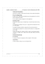
Selection of I/O
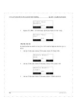
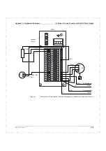
The potentiometer can be connected to AI1 and AO1. Jumper 1 must therefore be
closed.
The pressure transmitter PT1 does not have its own power supply and therefore
must be fed from the controller. The pressure signal is connected to AI2.
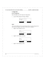
The high and low alarms is configured to DO1 and DO2.
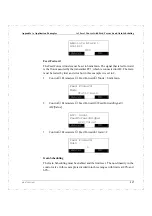
The motor is controlled by means of the three state pulse output on DO3, DO4,
increase and decrease.
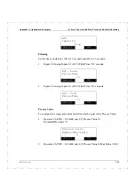
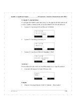
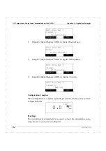
The Autotuner is used to set the PID parameters for this application.
Electrical Installation
Power Wiring
For details of the power wiring please refer to chapter 2 of this manual.
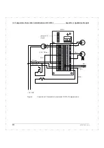
Signal Wiring
Connect the signal wiring as shown in the figure below.
Summary of Contents for ECA06
Page 1: ...Version 1 05 ECA06 60 600 EMA60 Configuration and Installation ...
Page 2: ......
Page 3: ...ECA06 60 600 EMA60 Configuration and Installation ...
Page 10: ...Contents vi 493 0736 11 6 2 ...
Page 16: ...1 5 Version information Chapter 1 Introduction 16 493 0736 11 6 2 ...
Page 200: ...4 2 Annual Check Chapter 4 Maintenance 200 493 0736 11 6 2 ...
Page 286: ...Appendix A Configuration Work Sheets 282 493 0736 11 6 2 ...
Page 304: ...B 1 Total Reset Appendix B Special Modes 298 493 0736 11 6 2 ...
Page 308: ...Index 302 493 0736 11 6 2 ...
Page 309: ......

