A.3 Communication Facilities
Appendix A: Communication
286
493-0736-11 (6-2)
Data Characters
– This section of the message contains the transmitted
characters specified by the Number of Characters. The value in the 16 bit registers
are sent in two bytes. Byte 1 which is sent second is the data character with the
lowest number. The bits in the register are sent in reverse order. The most
significant bit in the register is sent as the least significant bit of byte 2, as shown
in the example. The least significant bit in the register is the most significant bit
of byte 1.
Example: The value loaded in register A is:
ETX
– End of text (03H), indicates the end of message.
BCC
– block check count. This is a checksum calculated as the module 2 addition
(XOR) of each character in the message, except the initial STX-character.
A.3 Communication Facilities
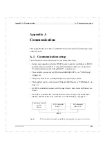
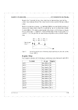
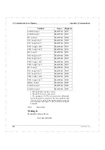
A supervisory control system can read and write bits or register words located in
the communication memory area of the ECA controller (see "Communication
Area Mapping", on page cclxxxv). The communication facilities are listed below.
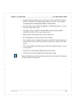
• All available analog and digital signal values can be read by a supervisory
system. The signals must be connected via communications buffers of type
AOC (Analog Output Communication) and DOC (Digital Output
Communication).
30
10
32
9
24=18H=
0
0
0
0
0
0
8
1
1
1
1
1
1
1
1
1
1
1
15
1
1
1
1
1
1
1
1
1
1
1
1
1
1
1
1
1
15
7
7
8
7FFD (50%)
Byte 1
Byte 2
Summary of Contents for ECA06
Page 1: ...Version 1 05 ECA06 60 600 EMA60 Configuration and Installation ...
Page 2: ......
Page 3: ...ECA06 60 600 EMA60 Configuration and Installation ...
Page 10: ...Contents vi 493 0736 11 6 2 ...
Page 16: ...1 5 Version information Chapter 1 Introduction 16 493 0736 11 6 2 ...
Page 200: ...4 2 Annual Check Chapter 4 Maintenance 200 493 0736 11 6 2 ...
Page 286: ...Appendix A Configuration Work Sheets 282 493 0736 11 6 2 ...
Page 304: ...B 1 Total Reset Appendix B Special Modes 298 493 0736 11 6 2 ...
Page 308: ...Index 302 493 0736 11 6 2 ...
Page 309: ......

