Page 13
© 2021 ABB. All rights reserved. Micro
-
BDCBB_QSG Rev. 04
Connecting The RS485 (GP) Communication Bus
For Standalone controller to VIM1 operation, make sure the controller
’
s appropriate RS485 GP communication
reference lead is properly connected to the correct DC bus potential prior to making the communication cable
connections. As with the jumper settings, this reference lead (Part of the power cable connection) either connects
to the DC
-
or DC+ bus based upon rectifier connectivity or Standalone operation. The RS485 GP Communication
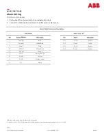
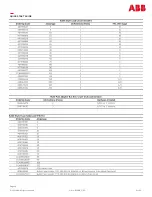
reference lead is found on pin 2 of J9 on the Pulsar Plus NE843 controller or pin 3 of P6 on the Millennium 2
controller. Connect/Verify reference lead connection per table below. Consult appropriate controller manuals or
technical field support for additional information as required.
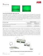
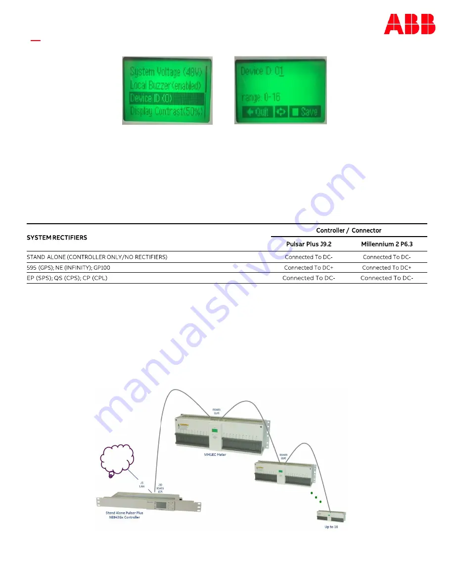
Figure 12 Standalone Pulsar Plus Monitoring VIM1 ED83368 Panels
With the system controller connections verified, VIM1 jumpers and ID properly set, and both units powered, the
VIM1 is ready to be connected to the controller
’
s system communication bus. For Standalone Controller
configurations, the communication connection can be made by simply using straight
-
thru cat
-
5 style cable to
connect between one of the RS485 ports on the VIM1 to port J10 on the Pulsar Plus (Figure 12) or on P9 for the
Millennium 2. Use the second VIM1 RS485 port to connect additional VIM1 in a daisy
-
chain fashion. Note: Although
not needed in many cases, it is recommended for long cable runs
(>50’)
with multiple VIM1s (>5) that the last VIM1
connected have a RS485 bus termination resistor 450050642 installed in the unused RS485 port. In power systems
with ABB rectifiers managed by a system controller, the communication connection may not be directly to the
controller and will have the be looked at on a per systems basis.
QUICK START GUIDE


