IEC 60870-5-101 and IEC 60870-5-104
Functions
Interface
Link state
Link speed
Signal quality
Port state
fo1
132
164
196
228
fo2
133
165
197
229
console0
134
166
198
230
console1
135
167
199
231
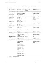
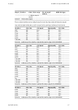
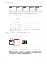
Table 31:
Addresses of the interface related information objects for 500NMD20
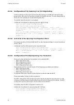
Commands to modify pre-set object addresses
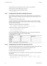
< s e t { i e c 1 0 1 | i e c 1 0 4 } i n t e r f a c e { 1 | 2 } o b j e c t a l a r m
a d d r e s s - b a s e { 0 - 1 6 7 7 7 2 1 5 } >
< s e t { i e c 1 0 1 | i e c 1 0 4 } i n t e r f a c e { 1 | 2 } o b j e c t r t s - i n
a d d r e s s { 0 - 1 6 7 7 7 2 1 5 } >
< s e t { i e c 1 0 1 | i e c 1 0 4 } i n t e r f a c e { 1 | 2 } o b j e c t c t s - o u t
a d d r e s s { 0 - 1 6 7 7 7 2 1 5 } >
< s e t { i e c 1 0 1 | i e c 1 0 4 } i n t e r f a c e { 1 | 2 } o b j e c t d c d - o u t
a d d r e s s { 0 - 1 6 7 7 7 2 1 5 } >
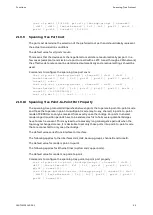
< s e t { i e c 1 0 1 | i e c 1 0 4 } i n t e r f a c e { 1 | 2 } o b j e c t l i n k s t a t e
a d d r e s s - b a s e { 0 - 1 6 7 7 7 2 1 5 } >
< s e t { i e c 1 0 1 | i e c 1 0 4 } i n t e r f a c e { 1 | 2 } o b j e c t l i n k s p e e d
a d d r e s s - b a s e { 0 - 1 6 7 7 7 2 1 5 } >
< s e t { i e c 1 0 1 | i e c 1 0 4 } i n t e r f a c e { 1 | 2 } o b j e c t s q a d d r e s s -
b a s e { 0 - 1 6 7 7 7 2 1 5 } >
< s e t { i e c 1 0 1 | i e c 1 0 4 } i n t e r f a c e { 1 | 2 } o b j e c t p o r t s t a t e
a d d r e s s { 0 - 1 6 7 7 7 2 1 5 } >
2.22.2
Connection of Signals and Application as RTU
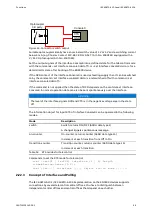
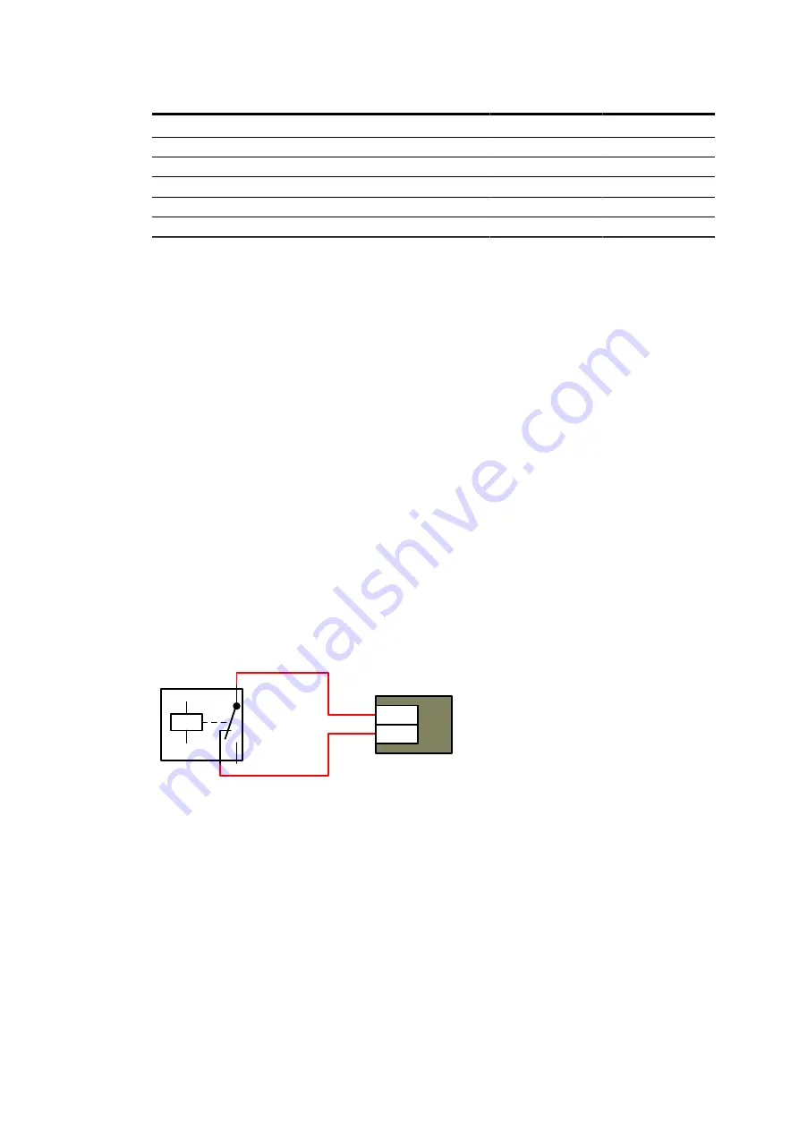
For the assignment of the interface Console0 see Chapter 2.20, "Serial Interfaces". Input RTS
and output CTS can be connected to relai contacts (refer to "Fig. 23: Connector alarm relais")
to connect EDS500 with a potential free contact.
CTS
Console0
Alarm relay
RTS
3rd party
Figure 23: Connector alarm relais
The circuit shows CTS as power source. You have to take care that CTS is switched on
because only then RTS will be triggered when the relay switch is up. If CTS should be kept as
switchable output then the contact DCD of the interface Console0 can be used. DCD also has
to be switched on.
If CTS is to be used as switched output then the contact has to be connected to a potential
isolated converter (refer to "Fig. 24: Connector switch output"). This is usually an optocoupler
or a triggered switch. Take care of the maximum current of 5 mA.
68
1KGT151021
V000 1

