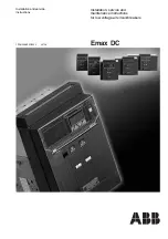
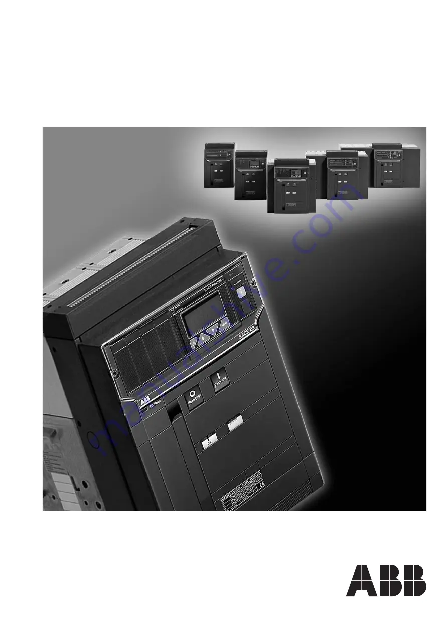
background image

Emax DC

Installation, service and
maintenance instructions
for low voltage air circuit-breakers

Installation and service
instructions

1SDH000635R0002      L3728

Summary of Contents for Emax DC L3447

Page 1: ...Emax DC Installation service and maintenance instructions for low voltage air circuit breakers Installation and service instructions 1SDH000635R0002 L3728 ...

Page 2: ...7 Emax DC ABB SACE L3728 Doc no Model Apparatus Dwg Title App Resp Off Take over Off Scale Language en 1SDH000635R0002 Installation service and maintenance instructions for low voltage air circuit breakers ...

Page 3: ...bbreviations and notes 29 12 SACE PR122 DC Release Identification page 30 12 1 Standard 30 12 2 Specifications 30 12 2 1 General 30 12 2 2 Auxiliary power supply 31 12 2 2 1 Powered by PR120 V PR120 LV module 31 12 2 3 Environmental characteristics 31 12 2 4 Description of inputs outputs 31 12 2 4 1 Binary inputs 31 12 2 4 2 Binary outputs 31 12 2 5 Communication bus 31 12 2 6 Protection functions...

Page 4: ...60 13 3 Putting into service 60 13 3 1 Connections 60 13 3 2 TC connection test 60 13 3 3 Test 60 13 3 4 Checking connections 60 13 3 5 Initial settings page 61 13 3 6 Password management 61 13 3 7 Checking the direction of power transmission 61 13 3 8 Replacing an electronic release 61 13 3 8 1 Installation 61 13 3 8 2 Uninstalling 61 13 4 User interface 62 13 4 1 Use of pushbuttons 62 13 4 2 Rea...

Page 5: ...ger recorder 87 15 2 1 General characteristics 87 15 2 2 Description of the Data Logger menu 87 15 2 2 1 Enabling the Data Logger 87 15 2 2 2 Setting the sampling frequency 87 15 2 2 3 Setting the standard stop events triggers 87 15 2 2 4 Setting and viewing customized stop events triggers 87 15 2 2 5 Setting the stopping delay 88 15 2 2 6 Restart Stop Data Logger 88 15 2 3 Recording time windows ...

Page 6: ...L3447 EmaxDC 4 108 L3728 Doc No Model Apparatus Scale Page No 1SDH000635R0002 ...

Page 7: ...terminals for connection to the power circuit in the withdrawable version the circuit breaker comprises the moving part of the apparatus which is completed with a fixed part fitted with terminals for connecting to the power circuit of the installation The moving part and fixed part are coupled by means of special clamps installed in the fixed part For details about the plant application of SACE Em...

Page 8: ...being put into service after checking it on receipt it must be put back in its container and covered with a waterproof sheet Caution Use a dry dust free room free of aggressive chemical agents as a storage room Position the circuit breaker and any fixed part on a horizontal surface not in direct contact with the floor but on a suitable support surface Fig 5 The maximum number of stackable circuit ...

Page 9: ...orrosive room and in such a way that it is not subject to shocks or vibrations Where this is not possible install it inside a switchboard with a suitable degree of protection For the preparation of the installation room please refer to the Overall dimensions paragraph whichgivesinformationonthefollowingpoints minimum installation volumes of the circuit breakers and derived versions distances to be...

Page 10: ... accordingtothenameplatediagram 4 3 2 Installation of the fixed part Fig 12 Attach the fixed part by means of the screws 1 washers 2 and nuts 3 M8 x 16 supplied by ABB SACE if other screws are used make sure that the head of the screws does not extend more than 5 5 mm from the base of the fixed part 4 3 3 Installation of the fixed part on board a ship Fig 11 Regarding the fixing points of the SACE...

Page 11: ...ng points whereas there are six for E4 E6 4 4 Installation of the flange on the compartment door Fig 13 Make the compartment door drillings specified in the Overall dimensions paragraph Attach the flange 1 on the front of the compartment door fixing it from the inside by means of the self tapping screws 2 Fig 13 Fixed circuit breaker Note The drawings are provided to show the type of terminal in g...

Page 12: ... to that of the terminal are allowable as shown in the following examples Fig 16 Positioning the first anchoring baffle of the busbars according to the short circuit current Anchoringtotheswitchgear Fig 17 Vertical terminals Circuit breaker Iu A Continuous current Busbar cross section carrying capacity A mm2 45 C 55 C E2B 800 800 800 800 1x 60x10 E2B 1000 1000 1000 1000 1x 80x10 E2B 1250 1250 1250...

Page 13: ...the insulating parts excessively applying the tightening torque indicated in Fig 18 Check tightness after 24 hours Fig 18 5 2 Earthing The fixed circuit breaker and the fixed part of the withdrawable circuit breaker have one or two terminals on the rear marked with the special symbol for connection to earth Fig 9 and Fig 12 Each terminal is complete with a bolt for fixing the connection A conducto...

Page 14: ...rical circuit diagram The terminals of the fixed connector are immediately accessible when the compartment door is open Furthermore a terminal box identified by code XF is available for connecting the position contacts of the moving part in relation to the fixed part The connector and terminal box have screw terminals E2 E3 E4 E6 5 contacts in position E4 E6 10 contacts in position E2 E3 10 contac...

Page 15: ...owing operations remove the front protection 3 of the release by taking action on the blocks 1 as shown in the figure remove the protection release 4 removing the side nuts 2 and then sliding the release out from the front of the circuit breaker Fig 21 Being of the two way type changeover contacts the auxiliary contacts can be modified from break contacts to make contacts and vice versa simply by ...

Page 16: ...ease at the corresponding rated voltage if any Supply the undervoltage release at the corresponding rated voltage and carry out the circuit breaker closing operation Disconnect voltage to the release Supply the undervoltage release at the corresponding rated voltage and carry out the circuit breaker closing operation Close the circuit breaker Supply the shunt opening release at the corresponding r...

Page 17: ...r the manual opening operation 2 Lever for manual loading of the closing springs 3 Mechanical indicator for circuit breaker open O and closed I 4 Mechanical indicator for protection release tripped on request 5 Pushbutton for the manual closing operation 6 Signalling device for springs loaded unloaded 7 Operation counter on request 8 Key lock on the closing operation 9 Mechanical indicator for cir...

Page 18: ...y starts reloading the springs again when the power returns It is in any case always possible to complete the reloading operation manually Fig 26 Press Fig 27 Press d Opening the circuit breaker For manual opening of the circuit breaker press pushbutton O 1 When there is a shunt opening release the operation can also be carried out remotely by means of the special control circuit Opening having ta...

Page 19: ...ing in operation to avoid any unnecessary stress C Before the racking in operation remove any padlock on the segregation shutter of the isolation terminals on the fixed part Fig 28 Press NOTES In relation to the fixed part the circuit breaker moving part can take up different positions identified as follows DISCONNECTED the moving part is inserted in the fixed part WITHOUT any connection between t...

Page 20: ...enance 8 1 Warning Before carrying out any maintenance work it is necessary to complete the following procedure open the circuit breaker and check that the operating mechanism springs are unloaded in the case of withdrawable circuit breakers work with the circuit breaker racked out of the fixed part for action on fixed version circuit breakers or on fixed parts of withdrawable circuit breakers dis...

Page 21: ...2 Maintenance program Fig 32 8 3 Maintenance operations 8 3 1 Preliminary operations Remove the flange 1 of the release turning the screws 2 as shown in the figures Remove the front escutcheon plate 3 by removing the four screws 4 Remove if present one or both side guards 5 by removing the front 6 and lateral 7 screws Remove the arcing chambers 8 by removing the screws 9 Maintenance operations Int...

Page 22: ...s Problem found Presenceofdustontheinternalparts Springsdeformedorrusty Safetyringsoutofplace nutsorscrewsloose Wiresandstrapsdetached Tracesofwear Incorrectadjustments distanceA Fig 33islessthan 1 mm forE2 E3orlessthan0 8mmforE4 E6 Presenceoffumesordust Presenceofcracksintheexternalplasticstructure Excessivedifferenceinwearbetweenthefirstandlast arcextinguishingplate Presenceofdustordirtontheinsu...

Page 23: ...aph 8 3 2 Lubricate the bearings of the drive shaft with MU EP1 AGIP grease including those on the sides of the circuit breaker Equivalent greases ESSO Beacon EP1 BP LTX1 SHELL AVANIA GREASE R1 KLUBER LUBRIFICATION CENTO PLEX 2P Lubricate the small opening and closing shafts and the hooks with 5 RX MOLY OLEOTECNICA grease Fig 33c Equivalent grease KLUBER LUBRIFICATION GRAFLOSCON A G 1 ULTRA Fig 33...

Page 24: ... Possible causes ConnectorXOnotinsertedcorrectly CoiloftheopeningreleaseYO1interrupted Defect in the electronic circuits of the microprocessor release The possible causes of tripping are listed in the part of the manualrelatingtothereleases Protectionsnotreset Operatingmechanismorconsentcontactsblockedinclosing position Auxiliarycircuitpowersupplyvoltagetoolow Differentpowersupplyvoltagefromtheone...

Page 25: ...ingrelease Reference figures in the electrical circuit diagrams YO 4 YC 2 YO2 8 Undervoltage release YU The undervoltage release opens the circuit breaker in the case of a considerable drop or lack of its power supply voltage It can be used for remote tripping by means of normally closed type pushbuttons as a lock on closing or to control the voltage in the primary and secondary circuits The relea...

Page 26: ...les a delay in the tripping of the release with preset adjustable times The use of the delayed undervoltage release is recommended when the power supply network of the release can be subject to power cuts or short lived voltage drops in order to avoid trips When it is not supplied circuit breaker closing is prevented The time delay device has to be combined with an undervoltage release with the sa...

Page 27: ...f the circuit breaker status open closed 4 10 or 15 auxiliary contacts The auxiliary contacts can have the following configurations 4 2 break make contacts for PR122 DC PR123 DC 2 normally open 2 normally closed 2 for the release 10 2 break make contacts for PR122 DC PR123 DC 5 normally open 5 normally closed 2 for the release 15 supplementary break make contacts which can be mounted outside the c...

Page 28: ... applied over the opening and closing pushbuttons prevent the corresponding circuit breaker operations except by using a special tool b IP54 door protection This is provided by means of a transparent plastic escutcheon plate which fully protects the front of the circuit breaker and ensures a degree of protection to IP54 Mounted on hinges it is fitted with a key lock Interlock between circuit break...

Page 29: ...alf busbars can be supplied be closed at the same time by a single transformer bus tie closed or simultaneously by both bus tie open D THREE a unit of 3 supplies a single only one of the three circuit breakers can closed circuit breaker Three supplies be closed generators or transformers on the same busbar for which parallel operation is not allowed 10 3 Spare parts The spare parts available are S...

Page 30: ...t O optional function unit function unit unavailable Notes 1 with internal PR120 D BT module 2 PR120 V or PR120 LV for standard see section 14 1 Function Unit PR122 DC PR123 DC Current protections L S I S S Current protections G S Additional protections U S Voltage protections UV OV RP S Other protections S2 S Temperature protection OT S S MCR protection S S Thermal memory S S Local bus for separa...

Page 31: ...mage 2 the unit does not function for example with autotest or with the trip test unit 3 the unit has been damaged in transit Prior to servicing and or replacing the circuit breaker must be open Also remember to disconnect all power supplies connected 11 1 1 Notes for dielectric stiffness tests Dielectric stiffness tests on the releases inputs and outputs are not permitted 11 2 Abbreviations and n...

Page 32: ...s user interface also enables parameter setup and complete the prealarm and alarm management for the protection and watchdog functions Complete with an instantaneous override protection that trips when the electronic release is not powered The protections available are Symbol Protection against L overload with inverse long time delay S short circuit with adjustable delay I instantaneous short circ...

Page 33: ...antaneous short circuit I 4 Protection against closing on short circuit MCR 5 Protection against instantaneous short circuit at high currents Iinst 6 Protezione override con relè non alimentato 7 Protection against overtemperature OT A timing indication message alarm LED is provided on the unit s display which is activated during a protection alarm It is disabled when the alarm condition ceases or...

Page 34: ...in the case where the curve with inverse time is selected This is based on the tS parameter defined as the trip time of the curve t2 selected at 1 5xI2 The other characteristics are the same as those for thermal memory L see par 12 2 9 1 1 12 2 9 2 2 Start up threshold S The start up function can be selected in the case where the curve with fixed time is selected The function can be disabled and i...

Page 35: ...nction can be selected The function can be enabled from the menu on the protection I page The function behaves in exactly the same way as the protection S see par 12 2 9 2 2 12 2 9 4 Protection MCR against closing on short circuit The MCR function is used to protect the system against closing if any on short circuit This protection goes on when the CB is closed within a time window ranging from 40...

Page 36: ...IEC 60255 8 step 0 01xIn t1 3I1 1 05 and1 2 xI1 20 Ig 4In S 0 6 xIn I2 10xIn 0 05 s t2 0 35 s step 0 01s 7 Ig 6 In The best of the two data t k step 0 1xIn 0 10 s t2 start up 30 s step 0 01s 10 Ig 6 In 10 o 40 ms 0 6 xIn I2 start up 10xIn 0 04 s t2 sel 0 20 s step 0 01s step 0 1xIn S 0 6xIn I2 10xIn 0 05 s t2 0 35 s 7 Ig 6 In 15 Ig 4In t k i2 step 0 1xIn step 0 01 s at 10xIn 10 Ig 6 In 20 Ig 4In I...

Page 37: ...aratus 1SDH000635R0002 L3728 12 2 10 Trip curves The trip curves given are for guidance and only show a sub group of the possible selections see par 12 2 9 7 12 2 10 1 Trip curves for functions L S t k i2 I 12 2 10 2 Trip curves for functions L S t k I ...

Page 38: ...assword see par 12 4 4 Select the value of the first figure between 0 and 9 by means of the and keys and press to confirm the figure and then move on to enter the next one After entering the fourth figure check the password you have entered If the password is correct you go from the READ state to the EDIT state If the password is wrong the message Wrong password appears and remains until the ESC k...

Page 39: ... must be used to perform the Trip test to view the information page and to see the last trip qualora abbia Ref Description 1 Voltage takeoff isolator 2 Busbar voltage LED 3 Pre alarm indicator LED 4 Alarm indicator LED 5 Graphic display the word ABB in the bottom left hand corner indicates normal operation 6 Serial number of the PR122 DC 7 Rating plug 8 Pushbutton for exiting the sub menus or for ...

Page 40: ...nfirm Cancel Change any changes you have made This procedure is not applicable to all the programming activities Two examples are provided below one concerns the case in which no confirmation is needed for the changes you have made while in the other a confirmation window appears Procedure not requiring the confirmation of any programming For instance to set the System Date the correct sequence is...

Page 41: ...s Menu 1 6 Overload S Protection I Protection L Protection Protections 1 3 Time t1 Thermal memory L Protection Threshold I1 Password Enter password 0 From the Main Menu select the item PROTECTIONS press the key enter From the Protections Menu select the item PROTECTION L press the key enter From the Protection L Menu select the item THRESHOLD press the key enter You will be prompted to input a Pas...

Page 42: ...he Main Menu the following box will appear Accept the new configuration Reject the new configuration the previous configuration is retained Change the previously input values To select the required option use the arrow down arrow up keys and press enter to confirm 1 3 Confirm Abort Modify Confirm Programming Note To set the system language check that the relay is set to local when PR120 D M is ins...

Page 43: ... disabled CB status Test 4 6 Device test SIGNALLING module COM module Zone selectivity Test 1 5 Protections settings Measurements Settings Protections Menu Contact wear Historicals Measurements 2 5 Measures graphics harmonics Measurements Settings Protections Menu 3 5 General settings Measurements Settings Protections Menu Hw Treip Modules Circuit Breaker Settings 1 7 Measurement interval System a...

Page 44: ... with the protection L as in the example Example of how to select the Threshold I1 Similarly to access the menus for the other protections see the Protections Menu table below 13 5 2 1 Protections menu table Protection Parameter Function L Curve Threshold I1 Thermal memory ON OFF S Enable ON OFF Curve Threshold I2 Time t2 Zone selectivity ON OFF Selectivity time Enable StartUp ON OFF StartUp thres...

Page 45: ... 4 Settings Menu The configuration parameters in the Settings menu are password protected 3 5 Protections settings Measurements Protections Menu Settings 1 9 Circuit breaker settings Hw Trip Modules Circuit Breaker Settings Installation Circuit Breaker Install Circuit Breaker 21 2 Uninstall Enter Enter PWD Parameter Function Values Notes Circuit breaker Installation Install Uninstall Hw trip Enabl...

Page 46: ...OM module the state of the springs and the position of the CB and in this submenu you can make the CB open or close Using the Trip Test function lets you view the disabling enabling of the Trip If it is enabled the circuit breaker is opened The function is only available with a busbar current of nil use Vaux PR030 B or PR010 T On the page only with Vaux you can also see the state of the circuitbre...

Page 47: ...The alarm message 100 wear alarm LED lighting up indicates that it is necessary to check the state of contact wear The percentage of wear depends on the number of openings carried out by the circuit breaker and by the absolute current interrupted during each of them 12 6 2 Electrical signals K51 p1 p4 Programmable electrical signals if the PR120 K module is installed and there is an auxiliary powe...

Page 48: ...nconsistency 12 6 3 Table of error and warning messages All the messages which can be shown on the display relating to incorrect configurations generic alarms or deriving from the protection functions and linked to useful information are described below The following symbols in the warning signals have the following meanings Warning signal Protection in alarm mode with no trip trip off Protection ...

Page 49: ...of expected data out of range 10 The expected trip does not occur Trip function disabled FN enable trip if necessary 11 No display Vaux missing the buffer FN see 12 5 6 1 of the opening data capacitor is discharged 12 The password is not requested The password has been disabled FN re enter the password with a value other than 0000 13 Impossible to change any PR122 DC in alarm situation FN paramete...

Page 50: ...ng the range of information available to user By means of the ABB SACE SD Pocket communication software the values of the currents flowing through the circuit breakers the value of the latest 20 interrupted currents and protection settings can be read 12 8 3 PR021 K and HMI030 units The PR122 DC can also be connected to the optional external PR021 K unit see par 15 1 to indicate through potential ...

Page 51: ... G earth fault with adjustable delay U current unbalance OT temperature out of range UV undervoltage OV overvoltage RP reverse active power MCR closing on short circuit The PR123 DC can be installed on 3 pole CBs or on 4 pole CBs The unit opens the circuit breaker in which it is installed by means of the TC which takes effect directly on the device s mechanical leverism The protection unit is self...

Page 52: ...Zone selectivity output for protection G only with Vaux Note These inputs outputs can be used between PR122 PR123 series units only 13 2 5 Communication bus Local internal bus on rear connector RS485 physical interface Modbus protocol External system bus RS485 physical interface Modbus RTU protocol baud rate 9600 19200 bps Test bus on front test connector 13 2 6 Protection functions The PR123 DC p...

Page 53: ... IEC standard 60255 8 The protection trip time inverse time is given by the expression τ where If is the fault current and I1 the protection threshold NB Time expressed in seconds 13 2 9 1 1 Thermal memory L The thermal memory can be enabled to protect the cables on the basis of the hot state tripping curve in IEC 60255 8 where Ip is calculated on the basis of the evolution of the current providin...

Page 54: ...ld must only be earthed on the circuit breaker of the supply side relay ZSI side The operation is only guaranteed when there is an auxiliary voltage The following logical table is implemented to manage the Zone Selectivity Input ZSI and Zone Selectivity Output ZSO signals Zone selectivity Imax I2 ZSI signal ZSO signal Trip T Excluded NO 0 0 No trip Excluded NO 1 0 No trip Excluded YES 0 0 t2 progr...

Page 55: ...trips in the case when for a time greater than or the same as the time t6 set an unbalance is determined between two or more polarity higher than the set threshold I6 Range 2 90 by 1 steps The percentage of unbalance is therefore calculated Unb 100 max min max I I I where Imax is the maximum and Imin is the minimum polarity current It is possible to disable the trip control of the protection Enabl...

Page 56: ...rcuit breaker open and the unit would therefore always be under timing When the circuit breaker is closed or the passage of a current is detected you pass immediately from the state of alarm to TRIP without timing 13 2 9 10 1 Protection UV When the minimum voltage drops below the set threshold U8 the protection counts down the preset time interval t8 and then opens 13 2 9 10 2 Protection OV When t...

Page 57: ...5s 10 The best of the two data t k step 1 10 or 40 ms OT Fixed Instantaneous 5 C _____ temp k defined by SACE Iinst Automatic defined Instantaneous by SACE UV 0 5xUn U8 0 95xUn 0 1s t8 5s step 0 1s 5 The best of the two data t k step 0 01xUn 10 or 40 ms OV 1 05xUn U9 1 2xUn 0 1s t9 5s step 0 1s 5 The best of the two data t k step 0 01xUn 10 or 40 ms RP 0 3xPn P11 0 1xPn 0 5s t11 25s step 0 1s 10 T...

Page 58: ...of measurements Type of measurement Standard operation range Range of values measured by the relay Range Tolerance Currents 0 05 12 In 0 3 4 In 5 Ground fault current 0 05 4 In 0 3 4 In 5 Voltages PR120 V 10 V 1000 V 70V 1000 V 1 PR120 LV 10 V 48 V 24 V 48V 1 Active power 0 02 16 Pn 0 3 6 Pn 2 5 ...

Page 59: ...paratus 1SDH000635R0002 L3728 13 2 10 Trip curves The trip curves given are for guidance and only show a sub group of the possible selections see par 13 5 2 13 2 10 1 Trip curves for functions L S t k I2 I 13 2 10 2 Trip curves for functions L S t k I ...

Page 60: ... Model Scale Page No Doc No Apparatus 1SDH000635R0002 13 2 10 3 Trip curves for function G 0 1 1 0 2 1 0 2 t s 1 10 10 1 1 10 102 103 104 10 2 x In 10 1 0 02 0 5 10 0 5 60 0 9 60 0 02 0 9 U 13 2 10 4 Trip curves for function U ...

Page 61: ...728 t s 10 1 10 2 1 10 102 103 104 0 3 0 5 0 7 0 9 1 1 1 3 x Un 0 1 0 5 0 95 0 5 0 95 10 0 1 5 5 UV t s 10 1 10 2 1 10 102 103 104 1 1 05 1 1 1 15 1 2 1 25 1 3 x Un 1 05 1 2 10 0 1 5 1 05 1 2 0 1 5 OV 13 2 10 5 Trip curves for function UV 13 2 10 6 Trip curves for function OV ...

Page 62: ... must appear if they do do not close the circuit breaker immediately and make the correct connections 13 3 3 Test Before putting into service a test can be conducted by means of the specific Auto test function which can be activated on the PR123 DC A positive result is shown on the display Then a test can be conducted on the whole TC chain again using the specific function Trip test A positive res...

Page 63: ...e Settings System menu 13 3 7 Checking the direction of power transmission To make sure the settings is right for the direction of power transmission disable the RP protection or enable the trip lock and with the circuit breaker closed and the minimum loads powered make sure the power measurement on the release s display is consistent with the configuration of the system If it is not consistent ch...

Page 64: ...n The modifiable fields can be filled in using the or keys and confirming with the key Once you have entered the page you need you can move from one value to another by using the or keys To change a value position the cursor over the value the modifiable field will appear in reverse i e white on a black background and use the key To confirm the programming of the previously configured parameters p...

Page 65: ...rogramming you need to Confirm Cancel Change any changes you have made This procedure is not applicable to all the programming activities Two examples are provided below one concerns the case in which no confirmation is needed for the changes you have made while in the other a confirmation window appears Procedure not requiring the confirmation of any programming For instance to set the System Dat...

Page 66: ... the Main Menu From the Main Menu select the item PROTECTIONS press the key enter From the Protections Menu select the item PROTECTION L press the key enter Date Enter password June 12 2007 Password Enter password 0 10 22 53 400A I V 690V 1 5 Protections settings Measures Settings Protections Menu 1 5 Protections settings Measurements Settings Protections Menu 1 15 Overload S Protection S2 Protect...

Page 67: ... Change system date Change system time Select system language To change the system password select the relevant menu item and press enter then you will be prompted to enter the OLD password and afterwards you can input the new one twice Press ESC twice to return to the Main Menu Before accessing the Main Menu the following box will appear Accept the new configuration Reject the new configuration t...

Page 68: ...Off 6 In 50 ms K Off 0 04 s 3 I On 4 In 4 G Off 0 2 In 0 4 s K Off 0 04 s On 5 U Off 50 5 s Off 6 OT Off 7 K LC1 Off 50 I1 8 K LC2 Off 75 I1 9 UV Off 0 9 Un 5 s Off 10 OV Off 1 05 Un 5 s Off 11 RP Off 0 1 Pn 10 s Off 12 Language Engl 13 PR021 K Off 14 Measuring module type HIGH VOLTAGE 15 Rated Voltage 500V 16 S startup Off 6 In 100 ms 17 I startup Off 4 In 100 ms 18 G startup Off 1 In 100 ms 19 P...

Page 69: ...sabled CB status Test 4 6 Device test SIGNALLING module COM module Zone selectivity Test 1 5 Protections settings Measurements Settings Protections Menu Contact wear Historicals Measurements 2 5 Measures graphics harmonics Measurements Settings Protections Menu 3 5 General settings Measurements Settings Protections Menu Hw Treip Modules Circuit Breaker Settings 1 7 Measurement interval System ast ...

Page 70: ...en you can select the functions associated with the protection L as in the example Example of how to select the Threshold I1 13 5 2 1 Protections Menu table Protection Parameter Function L Threshold I1 Time t1 Thermal memory ON OFF S Enable ON OFF Curve Threshold I2 Time t2 Zone selectivity ON OFF Selectivity time Enter Enter Percentage of the actual currents and voltages with respect to the rated...

Page 71: ... I Enable ON OFF Threshold I3 Enable StartUp ON OFF StartUp threshold StartUp time G Enable ON OFF Curve Threshold I4 Time t4 Enable Trip ON OFF Zone selectivity ON OFF Selectivity time Enable StartUp ON OFF StartUp threshold StartUp time U Enable ON OFF Function Currents Voltages Threshold I6 Time t6 Enable Trip ON OFF UV Enable ON OFF Threshold U8 Time t8 Enable Trip ON OFF OV Enable ON OFF Thre...

Page 72: ...arameter Function OT Enable Trip ON OFF Load control Threshold 1 Enable ON OFF Threshold Threshold 2 Enable ON OFF Threshold Threshold lw Enable ON OFF Threshold Note for an explanation of the characteristics of the single protections and their settings and corresponding curves see par 13 2 9 ...

Page 73: ... Protections settings Measurements Settings Protections Menu 1 9 Circuit breaker settings Main Frequency Modules Circuit Breaker Settings Installation Circuit Breaker Install Circuit Breaker 21 2 Uninstall Enter Enter 13 5 4 1 Settings Menu table Parameter Function Values Notes Circuit breaker Installation Install Uninstall Modules Module PR120 D M COM if any see par 13 5 4 2 2 PR120 K Signalling ...

Page 74: ...n the values 9600 and 19200 bit s The physical protocol provides for the options 8 E 1 8 0 1 8 N 2 8 N 1 The addressing can be selected as standard Modbus or ABB For further information on the PR120 D M communication MODULE see paragraph 14 2 in this manual 13 5 5 3 PR120 K SIGNALLING module For a thorough examination of the signalling module refer to the corresponding section of the module paragr...

Page 75: ...e opening data the date and time Using the i Test key makes the release show all these data directly on the display There is no need for an auxiliary power supply for this function With an auxiliary power supply the information is shown immediately on the display without the need to press the i Test key and remains displayed indefinitely until you press the key The information remains available fo...

Page 76: ...il TC disconnected Key plug error Current sensors disconnected Installation error The IEC 60947 2 Standard defines the timing threshold L for current 1 05 I 1 3 I1 13 6 3 Table of error and warning messages All the messages which can be shown on the display relating to incorrect configurations generic alarms or deriving from the protection functions and linked to useful information are described b...

Page 77: ...ilable Unavailable Function temporarily unavailable Invalid date Date has not been set Parameters revised Programming session concluded correctly Cancelled Programming session cancelled Failed Programming session rejected 13 7 Troubleshooting PR123 DC unit The following table lists a series of typical service conditions to help you understand and solve hypothetical faults or malfunctions Note 1 Be...

Page 78: ...r supply Vaux or battery or by pressing i Test if in self powering mode 2 Note down the type of circuit breaker number of poles any accessories connected In Serial Number see par 13 4 and the SW version 3 Prepare a brief description of the opening what LEDs and or indications were displayed when did it happen how many times was it always under the same conditions what type of load what voltage wha...

Page 79: ...o the Test position mode by turning the screw anticlockwise until you reach the end of stroke position After performing a dielectric stiffness test restore the isolator to its original position by turning it clockwise until you reach the opposite end of stroke because all the voltage protections are disabled while the isolator is in the test position At the end of the procedure make sure that the ...

Page 80: ... of the module is illustrated below 14 1 4 2 Table of submenus for the PR120 V PR120 LV module This menu is accessible using the path Settings Modules PR120 V module Parameter Function Values Notes Rated Voltage 100 V 1000 V Step 10 Power Normal This setting is used to determine the sign of the power flow Reverse value measured To check its consistency with the system perform the test described in...

Page 81: ...ting Events via thepath Measurements Historicals Events 14 1 4 4 4 Measurements This menu is for showing the following measurements I Max Maximum current P Max Maximum active power P Mean Mean active power U Max Max line voltage U Min Min line voltage Reset Reset measurements n 02 L Protection I1 625 A Jan 06 2007 08 52 11 733 Last Trip Time in hours and minutes when CB opened Meter counts progres...

Page 82: ...PR120 D M COM communication module is only powered by the relay if there is a 24V auxiliary voltage available 14 2 5 Connection Refer to fig 45 in the wiring diagram provided in this manual 14 2 6 Communication functions available The communication function on the PR122 DC PR123 DC releases with PR120 D M COM is listed in the table PR122 DC or PR123 DC PR120 D M COM Protocol Modbus RTU Physical in...

Page 83: ...ed N 4 LED associated with the signalling contacts 14 3 3 Releases complete with the module optional for PR122 DC optional for PR123 DC 14 3 4 Characteristics of the digital input The unit enables the digital input to be associated with the following functions enabling of an alternative set of parameters set B PR123 DC only outside trip control zeroing release trips resetting PR120 K contacts loca...

Page 84: ...ing module The figure shows two cases A and B in which the input s status is active in case A the input does not stay valid beyond the enabling delay so the associated action does not take place whereas in case B the action takes place after the preset delay 14 3 8 1 Input configuration settings You can select the level at which to consider the input enabled 1 low input enabling level 2 high input...

Page 85: ...one Load Lc2 Custom Load Lc1 Signal source Delay Enter password 0 00 s Absent NC NO NO NC 21 2 Password Enter password 0 Absent Active high Active low Polarity 21 2 External Trip Generic Function 21 7 Trip reset Set B Local Function Reset signalling Energy reset Delay Enter password 0 00 s 1 3 Active high Function Delay Polarity Input Latch 14 3 9 PR120 K module menu layout The menu layout relatin...

Page 86: ...es as an override protection when the release is not powered The value of the threshold depends on the circuit breaker as shown in the table below N B There is no need for the customer to make any connections or adjustments PR120 DC CB Threshold kA E2 800 2 5 E2 1000 2 5 E2 1250 5 E2 1600 5 E3 800 2 5 E3 1000 2 5 E3 1250 5 E3 1600 5 E3 2000 7 5 E3 2500 7 5 E4 1600 5 E4 2000 5 E4 2500 10 E4 3200 10...

Page 87: ...ts A Reset button enables you to zero the status of all the front optical signals and return the relays contacts to the resting position The unit also contains ten LEDs to display the following information Power ON auxiliary power supply on Tx int Bus flashing synchronized with dialogue with the Internal Bus Eight LEDs associated with the signaling contacts 15 1 2 Power supply Auxiliary power supp...

Page 88: ...rate delay before activating the contact NO NC NO NC Contact normally open NO or normally closed NC Latch ON OFF With the contact ON once it has been activated it stays switched A specific reset action is needed to reset it 15 1 5 2 Important note The unit must be connected to the PR122 DC or PR123 DC by means of an internal busbar with a shielded corded two wire cable see note A par 11 2 no more ...

Page 89: ...ord 15 2 2 2 Setting the sampling frequency On the menu you can specify the frequency with which the measurements are saved choosing from 4 fixed frequencies i e 600 Hz 1200 Hz 2400 Hz or 4800 Hz The maximum data recording times see also par 15 2 3 depend on the selected frequency and are illustrated in the following table Frequency RECORDING TIME 600 Hz 27 3 s 1200 Hz 13 6 s 2400 Hz 6 8 s 4800 Hz...

Page 90: ...indow is displayed The user can select the sampling frequency see par 15 2 2 2 the type of stop event trigger see par 15 2 2 3 and the stopping delay see par 15 2 2 4 so as to obtain the required pre trigger with respect to the selected event Depending on the selection you make the stopping delay may be nil or it may be lower or higher than the recording time as illustrated in the following figure...

Page 91: ...ger Time stamp of the stop event trigger day hour minutes seconds milliseconds 4 words Data logger max file which indicates which is the max file with consistent data Data logger max address which indicates the max address number of a block with consistent data The following information is recorded in the block for each sampling period 1 current sample IA 2 current sample IA2 available only with E...

Page 92: ...sequent stop commands on the data saving procedure STATUS Waiting trigger this means that the data logger is enabled and waiting for the occurrence of the event selected as the trigger Data Logger triggered this indicates that the trigger event has occurred and the data logger is still recording Data Logger stopped this means that the recording has been terminated either because it has been comple...

Page 93: ...ror or Trip Coil error x x 2688 LC1 alarm x x 2049 G alarm x 2306 UV timing x x 4124 UV or OV tripped x x 33672 CB connected and springs charged x x You can combine the status bits with and or logical functions within the same group of events byte For more detailed information refer to the Modbus Interface document 15 3 3 Standard events for the Data Logger function selectable from the relay Event...

Page 94: ...1 Inside edge of compartment door 2 Segregation where foreseen 3 Circuit breaker M10 fixing drilling use M10 screws 4 N 1 M12 screw E2 E3 or n 2 M12 screws E4 E6 for earthing included in the supply 5 Insulating or metal insulated wall E2 III View A E2 IV View A E2 E4 E3 E6 Iu 1250A Iu 1600A Iu 1250A Iu 1600A Iu 800A Iu 1000A Iu 800A Iu 1000A Fig 35 Tightening torque of the main terminals Nm 70 Tig...

Page 95: ... Basic version with rear terminals Fig 36 E4 III View A E4 IV View A E3 III View A Iu 2500A Iu 3200A Iu 1600A Iu 2000A Iu 2500A Iu 3200A Iu 1600A Iu 2000A Iu 2000A Iu 2500A Iu 800A Iu 1000A Iu 1250A Iu 1600A Tightening torque of the main terminals Nm 70 Tightening torque of the earthing screw Nm 70 ...

Page 96: ...la N Pag L3728 Fig 37 Fixed circuit breaker Basic version with rear terminals E3 IV View A E6 III View A E6 IV View A Iu 2000A Iu 2500A Iu 800A Iu 1000A Iu 1250A Iu 1600A Tightening torque of the main terminals Nm 70 Tightening torque of the earthing screw Nm 70 ...

Page 97: ...ala N Pag L3728 A B E2 400 490 E3 500 630 E4 700 880 E6 1000 1260 Compartment dimensions Compartment door drilling N 2 holes for IP54 protection Depth 3 POLES 4 POLES Fixed circuit breaker Fig 38 oles for passing through flexible cables for mechanical interlocks ...

Page 98: ...ed part Ø 10 drilling use M8 screws 4 N 1 M12 screw E2 E3 or n 2 M12 screws E4 E6 for earthing included in the supply 5 Run from connected for a TEST to isolated 6 Alternative drilling with 25mm pitch for fixing fixed part 7 Ventilation drilling on the switchgear E2 III View A E2 IV View A 3 POLES 3 POLES 4 POLES 4 POLES A B C D Fig 39 Tightening torque of the fixing screws 20 Nm Tightening torque...

Page 99: ...la N Pag L3728 Withdrawable circuit breaker Basic version with rear terminals Fig 40 E4 III View A E4 IV View A E3 III View A Tightening torque of the fixing screws 20 Nm Tightening torque of the main terminals 70 Nm Tightening torque of the earthing screw 70 Nm ...

Page 100: ...ala N Pag L3728 Withdrawable circuit breaker Basic version with rear terminals Fig 41 E3IV View A E6 III View A E6 IV View A Tightening torque of the fixing screws 20 Nm Tightening torque of the main terminals 70 Nm Tightening torque of the earthing screw 70 Nm ...

Page 101: ...N Pag L3728 A B E2 400 490 E3 500 630 E4 700 880 E6 1000 1260 Withdrawable circuit breaker Compartment dimensions Compartment door drilling N 2 holes for IP54 protection Depth 3 POLES 4 POLES Fig 42 Holes for passing through flexible cables for mechanical interlocks ...

Page 102: ... Apparecchio Scala N Pag L3728 E2 180 180 E3 234 234 E4 270 360 E6 360 486 Fixed version Withdrawable version Minimum distance between the circuit breaker and the switchgear wall Door drilling Compartment door mechanical lock Fig 43 A 3POLES 4POLES ...

Page 103: ...r module PR120 K K51 SZin Dfin Zone selectivity input for protection S only with Vaux and PR122 DC or PR123 DC release K51 SZout DFout Zone selectivity output for protection S only with Vaux and PR122 DC or PR123 DC release K51 YC Closing control from PR122 DC or PR123 DC electronic release with communication module PR120 D M K51 YO Opening control from PR122 DC or PR123 DC electronic release with...

Page 104: ...not be supplied simultaneously on the same circuit breaker 6 7 8 13 14 22 46 47 Notes A The circuit breaker is only fitted with the accessories specified in the ABB SACE order acknowledgement Consult this catalogue for information on how to make out an order B The undervoltage release is supplied for operation using a power supply branched on the supply side of the circuit breaker or from an indep...

Page 105: ...torwithautomatic breakingaction Switch disconnector Controlcoil general symbol Instantaneousovercurrentrelay Overcurrentrelaywith adjustable short time delay trip Galvanically separated converter Shielded cable conductors i e 3 conductors shown Conductorsorstrandedcables i e 3 conductors shown Connectionofconductors Makecontact Breakcontactwith automaticcircuit breaking Change overcontact Make pos...

Page 106: ...01 1 K51 XK10 2 D1 C1 B1 Q XO XO a1 b1 c1 d1 1 2 1 A1E A1I 1 2 XK11 B1I B1E PR123 DC PR122 DC 2 1 XK10 A1I A1E A2I A2E XK10 3 4 4 3 XK11 B2E B2I B1E B1I XK11 1 2 C1 b1 B2 c2 C2 A1 Q a1 A2 2 Y01 1 K51 2 B1 XO XO a2 c1 b1 1 PR123 DC PR122 DC 1 b2 d2 c1 a2 XO XO D2 B1 2 K51 1 Y01 2 A2 a1 Q A1 C2 c2 d1 D1 B2 b1 C1 2 1 XK11 B1I B1E B2I B2E XK11 3 4 4 3 XK10 A2E A2I A1E A1I XK10 1 2 PR123 DC PR123 DC PR...

Page 107: ...L3447 EmaxDC 105 108 Doc No Model 1SDH000635R0002 Apparatus Scale Page No L3728 Motor operating mechanism opening closing and undervoltage releases Signalling contacts ...

Page 108: ...L3447 EmaxDC 106 108 Doc No Model 1SDH000635R0002 Apparatus Scale Page No L3728 Signalling contacts ...

Page 109: ...8 Doc No Model 1SDH000635R0002 Apparatus Scale Page No L3728 PR123 DC PR123 DC PR122 DC PR122 DC Auxiliary circuits of the PR122 DC and PR123 DC releases Warning see note F PR123 DC PR122 DC PR120 D M communication module ...

Page 110: ...L3447 EmaxDC 108 108 Doc No Model 1SDH000635R0002 Apparatus Scale Page No L3728 PR123 DC PR122 DC PR123 DC PR122 DC PR120 K signalling module PR021 K signalling unit PR122 DC PR123 DC ...

Page 111: ......

Page 112: ...ergamo Italy Tel 39 035 395 111 Telefax 39 035 395 306 433 http www abb com Due to possible developments of standards as well as of materials the characteristics and dimensions specified in the present catalogue may only be considered binding after confirmation by ABB SACE ...

Reviews: