B2342
Emax VF
15/66
Doc. No
Model
Apparatus
Scale
Page No
1SDH000909R0001
7. Instructions for use
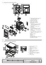
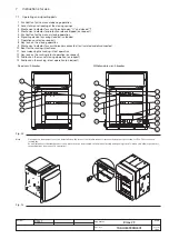
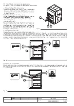
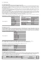
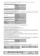
7.1. Operating and signalling parts
1 Pushbutton for the manual opening operation
2 Lever for manual loading of the closing springs
3 Mechanical indicator for circuit-breaker open “O” and closed “I”
4 Mechanical indicator for protection release tripped (on request)
5 Pushbutton for the manual closing operation
6 Signalling device for springs loaded - unloaded
7 Operation counter (on request)
8 Key lock on the closing operation
9 Mechanical indicator for circuit-breaker connected, test isolated and disconnected
10 Seat for the racking-in/out lever
11 Lever releasing the racking-in/out operation
12 Key lock on the racking-in/out operation (on request)
13 Padlock on the manual closing operation (on request)
14 Padlock on the racking-in/out operation (on request)
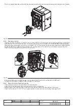
Fig. 23
1
8
2
3
4
6
5
7
1
8
2
3
4
6
5
7
10
11
9
12
14
13
Fixed circuit-breaker
Withdrawable circuit-breaker
Note
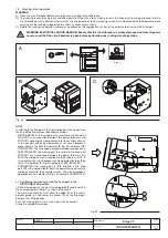
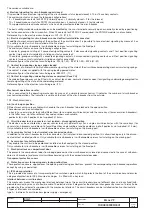
On request, a transparent cover can be installed on the front of the circuit-breaker to increase the degree of protection to IP54. The cover has a
locking key.
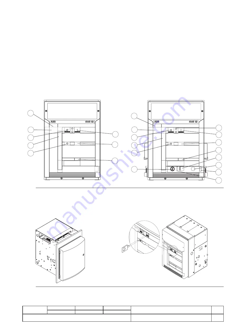
As an alternative to the transparent cover, a protection can be mounted on the manual closing and opening controls, which only allows operation of
the pushbuttons by means of a special tool.
Fig. 24


