background image

Maintenance Guide IM/AZ20M–EN Rev. B 

Endura AZ20 series probe

Combustion oxygen monitor

Summary of Contents for Endura AZ20 series

Page 1: ...Maintenance Guide IM AZ20M EN Rev B Endura AZ20 series probe Combustion oxygen monitor ...

Page 2: ...eader in process automation technology we offer customers application expertise service and support worldwide We are committed to teamwork high quality manufacturing advanced technology and unrivalled service and support The quality accuracy and performance of the Company s products result from over 100 years experience combined with a continuous program of innovative design and development to inc...

Page 3: ...mote Probe 14 5 6 Replacing the End Cap and Seal 15 5 6 1 Removing the End Cap 15 5 6 2 Fitting a New End Cap 15 5 7 Replacing the Diffuser Flame Arrestor and or Cell 16 5 7 1 Removing the Diffuser Flame Arrestor 16 5 7 2 Removing the Cell and C ring 16 5 7 3 Fitting a New C ring and Cell 18 5 7 4 Fitting the Diffuser Flame Arrestor 18 5 8 Replacing the Thermocouple Electrode Assembly 20 5 8 1 Rem...

Page 4: ...r 25 W 44 7 7 Thermocouple Electrode Assembly 44 7 8 Restrictor Kit 44 7 9 PT1000 Temperature Sensor 44 8 Illustrated Parts List Transmitter 45 8 1 Cartridge 45 8 2 AZ20 Integral Type 3 Probe Backplane 45 8 3 AZ20 Remote Type 4 Probe Backplane 45 Appendix A Connection Diagrams 46 A 1 AZ20 Integral Probe 46 A 2 AZ20 Remote Probe 47 Appendix B Probe Electrical Connections 48 B 1 AZ20 Probe Transmitt...

Page 5: ...in this manual or any relevant Material Safety Data Sheets where applicable may be obtained from the Company address on the back cover together with servicing and spares information Protective earth ground terminal Functional earth ground terminal Direct current supply only Alternating current supply only Both direct and alternating current supply The equipment is protected through double insulati...

Page 6: ...The European Waste Electrical and Electronic Equipment WEEE Directive 2002 96 EC that came into force on August 13 2005 aims to reduce the waste arising from electrical and electronic equipment and improve the environmental performance of all those involved in the life cycle of electrical and electronic equipment In conformity with European local and national regulations EU Directive 2002 96 EC st...

Page 7: ...ocedures for AZ20 probes both integral and remote versions and AZ20 ZFG2 replacement probes Kits containing all the parts required to complete a repair are identified in Section 7 page 42 probe and Section 8 page 45 transmitter 2 1 Earth to Probe Chassis Warning The installation of the instrument should be performed exclusively by personnel specialized and authorized to work on electrical installa...

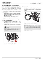
Page 8: ... multimeter 10 M input impedance on mV ranges 3 2 Pre check Requirements 1 The probe does not function properly unless the correct reference air is applied refer to the probe User Guide IM AZ20P EN 2 Isolate the probe transmitter system from mains power before performing checks Referring to Fig 3 2 3 At the probe unscrew and remove the end cap A and unplug the 9 way terminal plug B from the 9 way ...

Page 9: ...the thermocouple electrode assembly terminals B TC green and TC white for open or short circuit 3 Check that the thermocouple electrode assembly is isolated from the probe body earth If it is not isolated check for short circuits to earth in the probe s internal wiring 4 The resistance measured should be within the following range 5 If the measured resistance is out of range replace the thermocoup...

Page 10: ...ld be within the ranges shown in Table 3 3 3 If the measured resistance is out of range replace the PT1000 temperature sensor refer to Section 5 12 page 35 If the measured resistance is within range proceed to Section 4 Fig 3 5 Cell Isolation A B C Fig 3 6 Checking the ACJC Resistance C A B C 0 0 1 0 2 0 0 4 0 5 0 6 0 7 0 8 0 9 0 20 921 6 10 960 9 956 9 953 0 949 1 945 2 941 2 937 3 933 4 929 5 92...

Page 11: ...place the cell refer to Section 5 7 page 16 and or the thermocouple electrode assembly refer to Section 5 8 page 20 Warning Due to the presence of high voltage heater terminals wires 85 to 265 V in the probe head the probe s functional checks must be carried out by suitably trained personnel only refer to A in Fig 4 1 Fig 4 1 Live Heater Terminals in Probe Head Caution Functional probe checks are ...

Page 12: ...691 49 120 2 27 147 23 73 4 28 209 36 96 8 27 68 10 50 28 731 48 118 4 27 188 22 71 6 28 249 35 95 27 721 9 48 2 28 771 47 116 6 27 229 21 69 8 28 29 34 93 2 27 762 8 46 4 28 811 46 114 8 27 27 20 68 28 33 33 91 4 28 803 7 44 6 28 851 45 113 27 311 19 66 2 28 37 32 89 6 28 843 6 42 8 28 89 44 111 2 27 352 18 64 4 28 41 31 87 8 28 884 5 41 28 93 43 109 4 27 394 17 62 6 28 451 30 86 27 925 4 39 2 28...

Page 13: ...ectrode assembly may be faulty check this first refer to Section 4 2 page 9 or the cell may be faulty refer to Section 5 7 page 16 4 3 2 Detailed Cell Accuracy Check To perform this check calculate the span mV value first then calculate the O2 value from the span mV value 1 For millivolt readings and test gas management refer to steps 1 to 4 from Section 4 3 1 2 To calculate the span mV value a al...

Page 14: ...mp of 800 C For a certified test gas of 1 02 EmV 0 0496 x 800 273 16 log10 20 95 1 CmV EmV 48 2608 log10 20 95 1 CmV EmV 63 76 mV CmV 4 4 System Functional Check This section checks the AZ20 probe and associated transmitter for system functionality and accuracy 1 Perform a manual 2 point calibration using the 2 test gases selected refer to the probe User Guide IM AZ20P EN 2 If this fails check the...

Page 15: ...aintenance procedures Do not attempt to remove a probe unless the system it is used in has been shut down and isolated Do not attempt to remove a probe without approval from authorized personnel Before removing a probe from the flue prepare the flue for probe removal in accordance with relevant safety and site regulations Fit a blanking flange to the process if necessary Use lifting equipment with...

Page 16: ...required maintenance procedure s 10 To refit the probe refer to the probe User Guide IM AZ20P EN 5 5 Removing Refitting a Remote Probe 1 Isolate the remote transmitter from mains power supplies and label the isolator to prevent power being reconnected accidently 2 Isolate identify and disconnect gas supplies Referring to Fig 5 2 3 Unscrew and remove probe cover A 4 Disconnect all wires to terminal...

Page 17: ... Referring to Fig 5 3 1 Unscrew and remove probe end cap A 2 Remove seal and discard O ring B 5 6 2 Fitting a New End Cap Referring to Fig 5 3 1 Fix the new wiring label C to the inside of the end cap 2 Fit the new O ring onto the end cap ensuring it is seated correctly 3 Screw the new end cap onto the probe body until hand tight Warning If the end cap is replaced with the probe in situ ensure the...

Page 18: ...cell housing using minimal force If the cell can be withdrawn freely proceed to step 4 If the cell does not move is stuck in the probe body use a spanner on the 2 flats to rock it sideways gently until loose do not rotate more than 2 to 3 mm 0 08 to 0 12 in If this action frees the cell proceed to step 4 If the cell cannot be withdrawn freely and is welded to the thermocouple electrode contact ass...

Page 19: ...nitor Endura AZ20 Series Probe 5 Dismantling and Reassembly Probe IM AZ20M EN Rev B 17 Fig 5 4 Removing the Cell and C ring AZ20 Probe with AutoCal AZ20 Non AutoCal or AZ20 ZFG2 Replacement Probe Red Cell Green TC White TC ...

Page 20: ...stor F by aligning the internal notch G with the test gas pipe 2 Locate the 6 M4 x 50 bolts H and fit nuts I 3 Tighten the 6 M4 x 50 nuts and bolts using an M4 spanner and 3 mm A F hexagon wrench supplied Tighten opposing bolts evenly to a torque of 4 cNm 5 66 ozf in 4 At the probe head press the thermocouple electrode assembly spring locator J in and refit and tighten the M4 retaining screw K 5 R...

Page 21: ... Endura AZ20 Series Probe 5 Dismantling and Reassembly Probe IM AZ20M EN Rev B 19 Fig 5 6 Fitting a New C ring and Cell PT 1000 Red Cell Green TC White TC AZ20 Probe with AutoCal AZ20 Non AutoCal or AZ20 ZFG2 Replacement Probe ...

Page 22: ... sleeved wires D 4 If resistance is felt check if cell is welded to the helical contact at the end of the thermocouple electrode assembly refer to Section 5 7 2 page 16 step 3 When the cell has been released removed proceed to step 5 5 The thermocouple electrode assembly is very fragile so withdraw the thermocouple electrode assembly F from the probe body carefully providing support G along the le...

Page 23: ...ombustion Oxygen Monitor Endura AZ20 Series Probe 5 Dismantling and Reassembly Probe IM AZ20M EN Rev B 21 Fig 5 7 Removing the Thermocouple Electrode Assembly PT 1000 G A E D F Red Cell Green TC White TC ...

Page 24: ...l H 6 Using the correct PTFE colored sleeving supplied slide each sleeve onto the wire ends I Green TC thick wire non magnetic G White TC thick wire magnetic F Red Cell thin wire H 7 Pass 100 mm 4 in of sleeving into the last short insulator E Note To retain the uncoiled lead ends during fitting use a clamping block C constructed from a wooden board and 3 bulldog clips or use 3 weights Caution Do ...

Page 25: ...rs to prevent damage 13 Locate the M4 spring locator retaining screw O to secure the assembly 14 Reconnect the red Cell green TC and white TC sleeved wires P to the inner terminal block connections The 3 PTFE sleeved wires TC TC and Cell must be free to slide within the spring locator by up to 30 mm 1 2 in to allow for thermal expansion of the probe body during probe operation 15 AutoCal versions ...

Page 26: ...isconnect the Test Gas to Sensor tube F at the centre connection 5 Disconnect heater wires G from the terminal block blue and brown connections 6 If transmitter wires are present unscrew the terminal plug retaining screws H from terminal block s I and remove terminal plug s J from the socket s 7 Remove the 3 internal structure mounting plate M4 screws K using the 3 mm A F hexagon wrench supplied 8...

Page 27: ...ries Probe 5 Dismantling and Reassembly Probe IM AZ20M EN Rev B 25 Fig 5 10 Removing the Heater Assembly Test Gas Tube to Sensor Location on Probes Fitted with AutoCal Test Gas Tube to Sensor Location on Non AutoCal AZ20 and AZ20 ZFG2 Probes ...

Page 28: ...etaining tabs F back just enough to free the insulators along the complete length of the inner assembly 4 Remove each insulator G by sliding it over the heater wires 5 Release the heater assembly H from the inner assembly support column s I by folding the 4 tabs J on the heater assembly end plate back 6 Separate the heater assembly H from the inner support sections I 7 Discard the heater assembly ...

Page 29: ... the inner support assembly 5 Refit the 2 parts of the thermal barrier sections H and secure them using the length of wire I supplied Wind 2 turns and twist the ends together 6 Pass the 2 heater wires J through the openings in the internal structure mounting plate end plate K 7 Slide the red sleeve L over the heater wires until it butts up to the last insulator 8 Prepare the heater wires M for re ...

Page 30: ...its entire length and position the heater test gas hole C over the test gas tube A in the probe body Keep the assembly straight while positioning the oven in the probe body and ensure the test gas hole is not blocked with oven insulation To clear blockages use an air line from the cell end 4 Carefully slide the inner assembly B into the probe body until the end of the test gas tube D is visible th...

Page 31: ...e connection on the probe body AZ20 ZFG2 Replacement Probes only disconnect the internal Reference Air tube H connected to the internal conduit from the connection on the probe body 11 If AutoCal is fitted connect Test Gas 1 and 2 tubes I to the AutoCal manifold by pressing blue release ring J and connecting the tube 12 Connect the internal earth connection K 13 Re install the probe refer to the p...

Page 32: ...ug C from the socket 2 Disconnect the reference air tube D by pressing the blue release ring in and pulling the tube out If resistance is felt press and hold the blue release ring and push the tube into the connector then withdraw it 3 Disconnect test gas tube E from the centre connection 4 Check that the thermocouple electrode assembly is not welded to the cell refer to Section 5 8 1 steps 1 to 4...

Page 33: ...push the Solenoid Valve loom connections onto the Solenoid Valve terminals F as follows White Red SV2 COM to SV1 COM terminal White Blue SV2 White Red SV1 COM White Green SV1 5 Make Pressure Switch loom connections to the inner terminal block terminals G 6 Feed the Solenoid Valve loom wires under the internal structure mounting plate and make Solenoid Valve loom connections to the inner terminal b...

Page 34: ...ect the screen from terminal SCN connection to the internal earth connection K 15 Make AutoCal cable connections to the 6 way terminal plug L as shown in Table 5 3 Caution Test gas is applied to the probe continuously on AutoCal models All connections through to the AutoCal assembly inside the probe must be leak tight to prevent loss of test gas and contamination of reference air within the probe ...

Page 35: ...on the existing Commissioning Label T If a new cell has been fitted record the AutoCal upgrade details and the new cell data details on the new Commissioning Label and re calibrate the probe using the new cell data refer to the transmitter User Guide IM AZ20E EN 22 Re install the probe as detailed in the probe User Guide IM AZ20P EN 23 At the transmitter set the Calibrate AutoCal Hardware Hardware...

Page 36: ...e by the metal to metal faces of the restrictors inlets 6 Fit the 2 new larger test gas restrictors G into the TG1 and TG2 inlets on the casting and tighten fully using the 3 mm A F hexagon key Do not use thread sealant the metal to metal seal is sufficient 7 Fit the new smaller reference air restrictor H into the Ref Air inlet and tighten fully using the 2 5 mm A F wrench supplied Do not use thre...

Page 37: ...ntegral probe or Section 5 5 page 14 remote probe Remove the probe end cap as detailed in Section 5 6 1 page 15 Referring to Fig 5 20 1 Loosen the 2 ACJC connection terminal block screws A violet and grey terminal label and remove existing PT1000 sensor B 2 Connect the new PT1000 to the terminal block and tighten the 2 ACJC terminal block screws A 3 Refit the probe end cap refer to Section 5 6 2 p...

Page 38: ...cartridge retaining screws D to secure the cartridge E to the backplane F 7 Locate the transmitter cover B and tighten the 4 transmitter cover retaining screws A 8 Refer to the transmitter User Guide IM AZ20E EN to re configure the transmitter Warning Before dismantling the transmitter clean the outer surfaces of the transmitter thoroughly Handle internal components carefully keep them clean and e...

Page 39: ...ge refer to the probe User Guide IM AZ20P EN for recommended disposal procedures 5 Position a new cartridge over the backplane E align the cartridge retaining screws C with the 3 backplane screw access holes F and push the cartridge in gently to engage the connectors 6 Tighten the 3 cartridge retaining screws C to secure the cartridge D to the backplane E 7 Refit the transmitter cover B by screwin...

Page 40: ...ection 6 2 2 page 38 to fit a new backplane 6 2 2 Fitting a New Backplane Referring to Fig 6 4 1 Position the new backboard A in the probe s transmitter housing B 2 Tighten the 3 backplane retaining screws C to secure the backplane A to the probe s transmitter housing B 3 Reconnect the probe s signal connectors D ensuring they are plugged into the correct terminations 4 Proceed to Section 6 1 2 pa...

Page 41: ...he backboard C out of the probe transmitter housing D and discard the backboard refer to the transmitter User Guide IM AZ20P EN for disposal recommendations 5 Proceed to Section 6 3 2 to fit a new backplane 6 3 2 Fitting a New Backplane Referring to Fig 6 6 1 Position the new backboard A in the transmitter housing B 2 Tighten the 3 backplane retaining screws C to secure the backplane A to the tran...

Page 42: ... Blue 3 SCN Screen Screens 4 T C Thermocouple ve White 5 T C Thermocouple ve Green 6 ACJC PT1000 Cold Junction Compensation Grey 7 ACJC PT1000 Cold Junction Compensation Violet 8 CELL Oxygen Input ve Black 9 CELL Oxygen Input ve Red 10 PS2 Pressure Switch Gas 2 White Yellow 11 P COM Pressure Switch Common White Black 12 PS1 Pressure Switch Gas 1 White Orange 13 SV2 Solenoid Valve Gas 2 White Blue ...

Page 43: ...tputs terminal block B and current output and option board terminals terminal block G as required 5 Refer to Section 6 1 1 page 36 steps 5 to 8 to refit the cartridge and transmitter cover Warning The transmitter must be earthed Isolate the incoming mains power supply cable before making connections at the transmitter or the probe Fig 6 8 Remote Transmitter Power Supply and Output Connections C B ...

Page 44: ...efurbishment kit Table 7 4 page 43 Table 7 6 page 43 Refer to Section 5 10 page 30 5 AZ20 and AZ20 ZFG2 end cap Table 7 7 page 43 Refer to Section 5 6 page 15 6 Heater assembly includes insulators AZ20 heater assembly includes insulators AZ20 ZFG2 replacement probe heater assembly includes insulators Table 7 8 page 44 Table 7 9 page 44 Refer to Section 5 9 page 24 7 Thermocouple electrode assembly...

Page 45: ...test gas 2 2 Test gas tube to sensor 1 1 4 in NPT male pipe fitting 1 6 mm A F hex wrench 1 Table 7 4 AutoCal Upgrade Kit for NPT Fittings Part No AZ200 730 Item Quantity AutoCal manifold block assembly 1 AutoCal connection loom 1 6 Way terminal block with plug required for remote probes 1 M3 bolts 2 manifold 2 terminal block 4 Internal test gas connectors with air tight seals 2 Test gas tube test...

Page 46: ...lator kits comprise 0 5 m 1 64 ft kit part no AZ200 720 1 0 m 3 28 ft kit part no AZ200 721 1 5 m 4 92 ft kit part no AZ200 722 2 0 m 6 56 ft kit part no AZ200 723 1 Table 7 9 AZ20 ZFG2 Heater Assembly Replacement Kits Note Kits for probe lengths 0 5 to 2 0 m 1 64 to 6 56 ft can be used with AZ20 and AZ20 ZFG2 replacement probes Kits for probe lengths in excess of 2 m 6 56 ft can be used only with...

Page 47: ...backplane Table 8 3 Refer to Section 6 3 page 39 Fig 8 1 AZ20 Transmitter Replacement Kits 3 2 1 Item Quantity Replacement cartridge Replacement cartridge options comprise Standard cartridge kit part no AZ200 750 Standard cartridge plus analog outputs kit part no AZ200 751 Standard cartridge plus digital input output kit part no AZ200 752 1 Table 8 1 Cartridge Replacement Kit Item Quantity AZ20 in...

Page 48: ...een White Brown Blue Green Yellow Green Yellow 1 Heater 2 Heater 3 Earth 4 TC 5 TC 7 Cell 6 Cell 8 ACJC 9 ACJC 9 Way 2 Part Connector Violet Grey Red Black Green White Screens Brown Blue SV 1 SV 2 AutoCal Assembly AZ200 065 White Blue White Red White Green White Orange White Black White Yellow 15 SV 2 14 SV Common 13 SV 1 12 PS 1 11 PS Common 10 PS 2 6 Way 2 Part Connector Type 3 Integral Electron...

Page 49: ...V1 SV COM SV2 TB6 TB5 I O _ C B A Type 4 Remote Electronics AZ20 Probe Type 4 Backplane AZ200 260 PT1000 Red Black Green White Brown Blue 1 Heater 2 Heater 3 Earth 4 TC 5 TC 7 Cell 6 Cell 8 ACJC 9 ACJC 9 Way 2 Part Connector Violet Grey Red Black Green White Screens Brown Blue White Yellow White Black White Orange White Green White Red White Blue 10 PS 2 11 PS Common 12 PS 1 13 SV 1 14 SV Common 1...

Page 50: ...Pt1000 Cold Junction Compensation Red Cell Oxygen Input ve Black Cell Oxygen Input ve Green T C Thermocouple ve White T C Thermocouple ve Light Yellow SCN Screen Brown H Heater Blue H Heater Table B 1 Probe Transmitter Cable Connections Terminal Cable Color Tag ID Tx Connection Violet Not Used Grey Red Cell Oxygen Input ve Black Cell Oxygen Input ve Green T C Thermocouple ve White T C Thermocouple...

Page 51: ...al Connection White Yellow PS2 Pressure Switch Gas 2 White Black PS COM Pressure Switch Common White Orange PS1 Pressure Switch Gas 1 White Green SV1 Solenoid Valve Gas 1 White Red SV COM Solenoid Valve Common White Blue SV2 Solenoid Valve Gas 2 Table B 3 AutoCal Connections at Probe Fig B 2 AutoCal Connections at AZ20 Probe AutoCal terminal plug connected to AutoCal terminal block ...

Page 52: ...ressure Switch 1 Pressure Switch 2 White Orange PS1 White Black PS COM to 6 way Terminal Block White Yellow PS2 White Black PS COM to PS1 Tag Pressure Switch 1 2 Notes Refer to Table B 3 page 49 for solenoid valve terminal connections Solenoid valves have a maximum output of 100 mA 24 V DC protection and inline fuses are required if using external automatic calibration panels Fig B 4 AutoCal Solen...

Page 53: ...Combustion Oxygen Monitor Endura AZ20 Series Probe Notes IM AZ20M EN Rev B 51 Notes ...

Page 54: ...Combustion Oxygen Monitor Endura AZ20 Series Probe Notes 52 IM AZ20M EN Rev B ...

Page 55: ... Analytics Instrumentation pH Conductivity and Dissolved Oxygen Transmitters and Sensors Ammonia Nitrate Phosphate Silica Sodium Chloride Fluoride Dissolved Oxygen and Hydrazine Analyzers Zirconia Oxygen Analyzers Katharometers Hydrogen Purity and Purge gas Monitors Thermal Conductivity Customer support We provide a comprehensive after sales service via a Worldwide Service Organization Contact one...

Page 56: ...rd to purchase orders the agreed particulars shall prevail ABB does not accept any responsibility whatsoever for potential errors or possible lack of information in this document We reserve all rights in this document and in the subject matter and illustrations contained therein Any reproduction disclosure to third parties or utilization of its contents in whole or in parts is forbidden without pr...

Reviews: