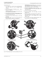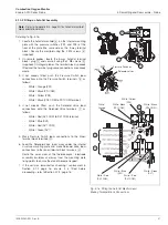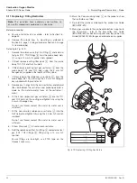
Combustion Oxygen Monitor
Endura AZ20 Series Probe
5 Dismantling and Reassembly – Probe
20
IM/AZ20M–EN
Rev. B
5.8 Replacing the Thermocouple /
Electrode Assembly
Before replacing the thermocouple and electrode assembly:
1. Ensure replacement thermocouple and electrode
assembly and C-ring kits are available – refer to Section
7.7, page 44.
2. Remove the probe from its mounting – refer to Section
5.4, page 14 (integral probe) or Section 5.5, page 14
(remote probe).
3. Remove the probe end cap as detailed in Section 5.6.1,
5.8.1 Removing the Thermocouple / Electrode Assembly
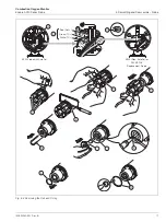
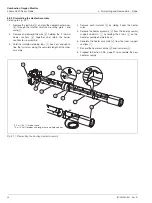
Referring to Fig. 5.7:
1. At the probe head, disconnect the red (Cell +), green (TC+)
and white (TC–) sleeved wires
A
from the inner terminal
block connections.
2. Unscrew and remove M4 screw
C
.
3. Check if the cell is welded to the electrode tip by gently
pulling the white and green sleeved wires
D
.
4. If resistance is felt, check if cell is welded to the helical
contact at the end of the thermocouple / electrode
assembly – refer to Section 5.7.2, page 16 (step 3). When
the cell has been released / removed, proceed to step 5.
5. The thermocouple / electrode assembly is very fragile, so
withdraw the thermocouple / electrode assembly
F
from
the probe body carefully, providing support
G
along the
length of the assembly and keeping it straight.
6. Lay the thermocouple / electrode assembly on a long
clean
flat surface.
7. Proceed to Section 5.8.2, page 22 to fit a new
thermocouple / electrode assembly.
Note.
Check all items including the extension insulators for
damage as they are removed. Keep items for reuse in a
clean safe place. Replace any damaged items with new
replacements. Never reuse damaged insulators.
Caution.
AutoCal versions only – if necessary,
disconnect the test gas to sensor tube
B
to allow
access to the terminal connectors.
Caution.
Do not pull the Cell + (red sleeve) wire
E
to check for thermocouple / electrode assembly play.

