Combustion Oxygen Monitor
Endura AZ20 Series Probe
5 Dismantling and Reassembly – Probe
30
IM/AZ20M–EN
Rev. B
5.10 Fitting AutoCal as an Upgrade
Before fitting the AutoCal assembly:
1. Ensure AutoCal upgrade and C-ring replacement kits are
available – refer to Section 7, page 42.
2. Remove the probe from its mounting as detailed in
Section 5.4, page 14 (integral probe) or Section 5.5, page
14 (remote probe).
3. Remove the probe end cap as detailed in Section 5.6.1,
4.
Integral probes only
– check that the AutoCal
connection wires are available at the probe head; these
should be accessible as an unconnected bundle – refer to
the probe User Guide (IM/AZ20P–EN) for cable details.
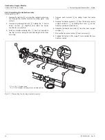
5.10.1 Accessing the AutoCal Mounting Plate
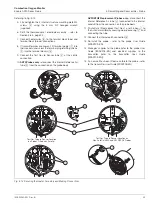
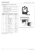
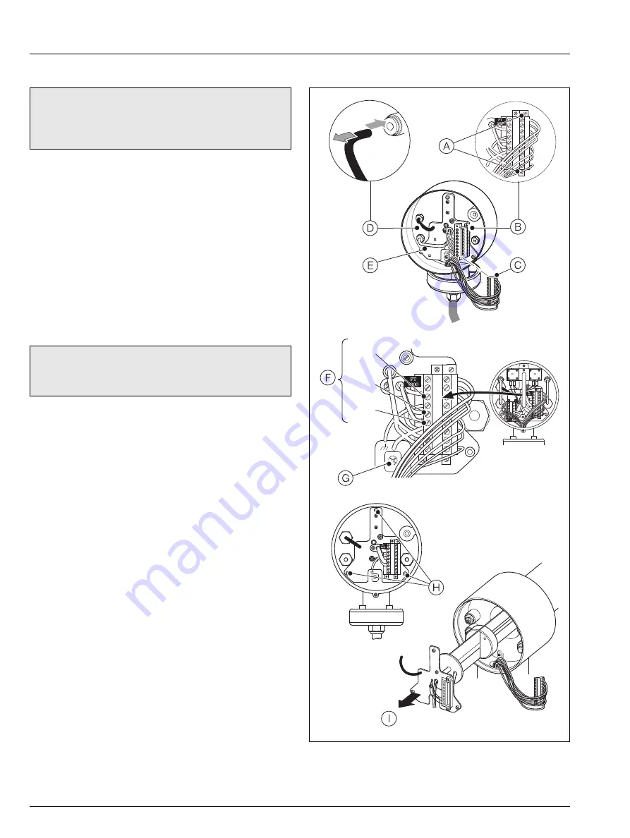
Referring to Fig. 5.15:
1. Unscrew the 2 x 9-way terminal plug retaining screws
A
from terminal block
B
and remove terminal plug
C
from
the socket.
2. Disconnect the reference air tube
D
by pressing the blue
release ring in and pulling the tube out. If resistance is felt,
press and hold the blue release ring and push the tube
into the connector then withdraw it.
3. Disconnect test gas tube
E
from the centre connection.
4. Check that the thermocouple / electrode assembly is not
welded to the cell – refer to Section 5.8.1, steps 1 to 4.
5. Disconnect earth wire
G
.
6. Remove the 3 internal structure mounting plate M4
screws
H
using the 3 mm A/F hexagon wrench
(supplied).
7. Carefully withdraw the inner assembly enough to allow
access to both sides of the internal structure mounting
plate
I
.
Note.
This procedure upgrades a standard AZ20 probe to
provide AutoCal capability (not applicable to AZ20/ZFG2
replacement probes). Refer to Appendix B.3 to B.5, pages
49 to 50 for further information.
Caution.
Check if the cell is welded to the end of the
thermocouple / electrode assembly – refer to Section 5.8,
page 20.
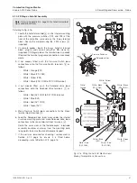
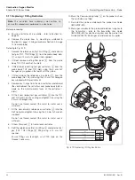
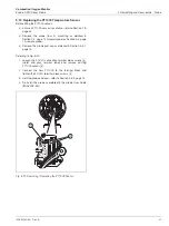
Fig. 5.15 Accessing the AutoCal Mounting Plate
Cell +
(Red)
TC +
(Green)
TC –
(White)


