background image

— 

A B B ME A SUR EMENT & A N A LY TIC S | COMMISSIONING INSTRUC TION | CI/A Z4 0 - EN R E V. A
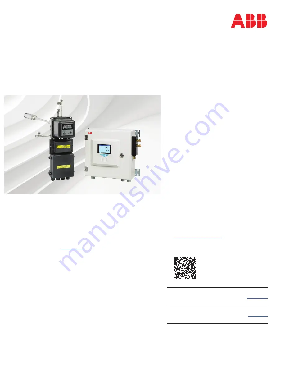
Endura AZ40

Oxygen and carbon monoxide equivalent (COe) analyzer

Measurement made easy

Introduction

This document provides unpacking, installation, 
connection, setup and basic operation details for 
the AZ40-EN analyzer system. For comprehensive 
product details, refer to Operating instruction 

OI/AZ40-EN

.

Contents

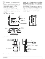
1  Overview / system dimensions .............................5

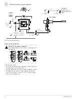
2  Environmental requirements .................................6

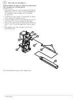
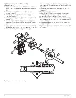
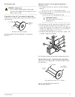
3  Mechanical installation ...........................................7

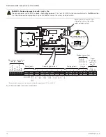
4  Electrical installation ............................................12

5  Pneumatic installation ..........................................18

6  System setup ..........................................................21

7  Calibration and sensor setup .............................. 28

8  Operation ............................................................... 30

9  Configuration (Advanced access level) ............. 34

For more information

Further publications for the Endura AZ40 analyzer 
are available for free download from:

www.abb.com/analytical

(see links and reference numbers below) or by 
scanning this code:

Search for or click on

Data Sheet

Endura AZ40

Oxygen and carbon monoxide 

equivalent (COe) analyzer

DS/AZ40-EN

Operating Instruction

Endura AZ40

Oxygen and carbon monoxide 

equivalent (COe) analyzer

OI/AZ40-EN

— 
Oxygen and carbon 
monoxide equivalent 
analyzer

Summary of Contents for Endura AZ40

Page 1: ...6 3 Mechanical installation 7 4 Electrical installation 12 5 Pneumatic installation 18 6 System setup 21 7 Calibration and sensor setup 28 8 Operation 30 9 Configuration Advanced access level 34 For more information Further publications for the Endura AZ40 analyzer are available for free download from www abb com analytical see links and reference numbers below or by scanning this code Search for ...

Page 2: ...llation operation maintenance and servicing of pressurized equipment must be performed by suitably trained personnel only in accordance with the information provided in this manual in accordance with relevant local regulations CAUTION Minor injuries This symbol in conjunction with the signal word CAUTION indicates a potentially dangerous situation Failure to observe this safety information may res...

Page 3: ...40 or equivalent with a level 3 particulate filter conforming to EN 143 or equivalent Disposable protective coveralls in accordance with Type 5 ISO 13982 1 2004 or equivalent Goggles and gloves DANGER Serious damage to health risk to life Pressurized equipment do not install remove the sensor probe if the process is at positive pressure Installation operation maintenance and servicing of pressuriz...

Page 4: ...n a product indicates a potential hazard which could cause serious personal injury and or death The user should reference this instruction manual for operation and or safety information This symbol when noted on a product indicates a potential hazard high temperature which could cause serious personal injury and or death The user should reference this instruction manual for operation and or safety...

Page 5: ...oint to provide analysis on a wet basis and prevent acid gases from condensing in the sample path Thermocouple inputs for process temperature measurement enable calculations of combustion efficiency Fig 2 Endura AZ40 transmitter main components dimensions Fig 3 Endura AZ40 sensor assembly main components dimensions Endura AZ40 Gas Analyser 85 240v AC 50 60Hz 730W Max TYPE No AZ40 XXXXXXXXXXXXXXX S...

Page 6: ...bject to shock loading for example close to ash hammers within 3 m 9 ft of steam or liquid process cleaning apparatus Fig 4 Environmental requirements 70 C 158 F Max 20 C 4 F Min 0 to 95 Humidity See page 35 for maximum probe temperatures and process pressure range 20 C 4 F Min 70 C 158 F Max 20 C 4 Min IP66 NEMA 4X IP55 NEMA 4 1500 mm 59 in approx 55 C 131 F Max 20 C 4 F Min CAUTION Damage to equ...

Page 7: ...readed end C of optional secondary filter 2 Thread primary filter assembly E and optional secondary filter assembly D onto probe shaft B 3 Thread the probe assembly with attached filter s onto the 1 4 inch NPT port F on sensor assembly G and tighten 4 Apply an anti seize compound suitable for temperatures up to 200 C 392 F to the threaded end of sensor aspirator H 5 Hand tighten exhaust filter ass...

Page 8: ...2 F to gland nut threads K 7 Slide probe shaft J into sealing connector L 8 Slide lava seal H bush G into sealing connector L then thread gland nut F onto sealing connector L and tighten finger tight 9 Adjust probe until the insulator cement joint just contacts gland nut F 10 Tighten gland nut F 1 2 a turn 11 Check probe J is held firmly If movement is detected carefully tighten gland nut F a furt...

Page 9: ...m 6 in or if mounted at a site where the temperature is 4 4 C 40 F 5 Temporarily cover opening G until the sensor probe filter assembly is ready for installation Preparing the stand off high temperature applications Refer to Fig 9 for flange options and recommended stand off pipe dimensions WARNING Bodily injury Ensure suitable lifting equipment and qualified personnel are available when mounting ...

Page 10: ...tallation Standard temperature probe ANSI 2 in flange version Referring to Fig 11 1 Remove 4 nuts and washers A from sensor assembly threads B 2 Feed probe filter assembly C through flange D and secure sensor body B to flange D using 4 nuts and washers A IMPORTANT NOTE If possible taper the exit hole C approximately 15 Fig 10 Mounting preparing the stand off high temperature applications 15º IMPOR...

Page 11: ...he transmitter Referring to Fig 14 1 Fix the transmitter A to a solid wall using 4 x fixings not supplied at location B Fixings must be capable of supporting a minimum weight of 7 6 kg 16 65 lb IMPORTANT NOTE Before installing the probe sensor assembly into the process complete transmitter installation as detailed on page 12 The sensor assembly must have all services connected with the transmitter...

Page 12: ... with equipment with no accessible live parts If the equipment is used in a manner not specified by the Company the protection provided by the equipment may be impaired The equipment conforms to Installation Category II of IEC 61010 All equipment connected to the transmitter s terminals must comply with local safety standards IEC 60950 EN61010 1 USA and Canada Only The supplied cable glands are pr...

Page 13: ...t sensor entry N and slide over sensor end O of mains power cable J in the correct orientation 9 Feed sensor end O of power cable J through entry N and connect to sensor terminal block P Refit cable gland if used at entry N 10 Check internal mains connector plug Q is plugged into the correct socket for the supplied mains voltage 115 V upper socket or 230 V lower socket 115 V upper socket 230 V low...

Page 14: ...is NOT a transmitter safety isolation switch and is fitted for operational purposes only Ensure mains connector is in correct position 115 V or 230 V for application Fig 17 Mains power cable connections 115 V 230 V High voltage power switch transmitter to sensor DO NOT USE AS A TRANSMITTER SAFETY ISOLATION SWITCH Line in Neutral in Earth Line out Neutral out Earth Line in Neutral in Earth ...

Page 15: ... lock transmitter door E using the supplied key 4 Fit a suitable cable gland conduit fitting at entry F 5 Feed sensor end G of signal cable C through entry F and connect to sensor terminal block H Secure with cable gland conduit fitting 6 Refit sensor cover I using 4 x sensor cover screws J 7 Proceed to page 16 for customer made input output connections Fig 18 Signal cable connections D green SCN ...

Page 16: ...ion 115 V or 230 V Fig 19 Customer made connections at transmitter DI1 DI2 DI3 DI4 AC COM DC COM 1 2 3 4 5 6 N C C N O N C C N O N C C N O N C C N O N C C N O N C C N O 1 2 3 4 1 2 3 4 5 V COM D D SCN 1 COM 2 TX RX 3 TX RX 4 TX 5 TX Line in Neutral in Earth Line out Neutral out Earth Digital inputs Relays digital outputs Analog outputs Comms Mains power connections see Fig 17 page 14 Signal connec...

Page 17: ...arth connection 115 V 230 V Signal connections see Fig 18 page 15 Mains power connections see Fig 17 page 14 Earth N L Blowback Blowback Inlet T C Inlet T C Screen Outlet T C Outlet T C Caution Maximum cable length 30 m 118 ft lengths over 30 m 118 ft require conduit or screen Caution Maximum cable length 30 m 118 ft Lengths over 30 m 118 ft require conduit or screen Earth ...

Page 18: ...sig Zero gas regulated to 1 bar 15 psig Pressure regulator set to 207 3 kPa 30 0 0 5 psig Test gas to sensor assembly 2 Stage coalescing filtration Test gas flowmeter Compressed air supply Instrument air supply to sensor assembly 350 to 700 10 kPa 50 0 to 100 0 1 5 psig Or IMPORTANT NOTE Slope tubing lines to sensor assembly 83 33 mm m 1 in ft minimum for a length of approximately 305 mm 1 ft 1 4 ...

Page 19: ...s must be as close as possible to 0 w w or v v it must not exceed 1 ppm w w or v v under normal operating conditions B Shut off valve C 2 Stage coalescing filtration self draining D Instrument air pressure regulator E 3 Way valve optional for maintenance purposes only not necessary for operation F Aspirator suction pressure port pressure required at port 51 7 to 65 5 kPa 7 5 to 9 5 psig G Aspirato...

Page 20: ...ent air turned off to obtain the duct pressure Verify that the sample duct is 5 to 5 kPa 20 to 20 inches H2O Turn the instrument air back on after taking this measurement Record the duct pressure in Table 4 6 Calculate the filter pressure drop by subtracting the sample pressure from the duct pressure Verify that the filter pressure drop is less than 2 kPa 8 inches H2O Record the filter pressure dr...

Page 21: ...using any of the following methods manually via the user interface automatically via the scheduled blowback remotely via digital input 2 DO2 remotely via MODBUS command Flow rate test 5 O2 To perform a flow rate test 5 O2 at the transmitter 1 From any Operator page press the key The Operator menu is displayed 2 Use the keys to scroll to the Enter Configuration menu and press the key The Access lev...

Page 22: ...rs with increase in flow rate Record the flow rate at which the mV reading first reached its stable value 8 Press the key below the Next prompt The following screen is displayed The span gas flow rate should be adjusted to the flow rate for stable mV value noted above plus a further 0 5 SCFH 0 25 l min 9 Press the key below the Next prompt The following screen is displayed Adjust the zero gas flow...

Page 23: ...vel screen 5 Press the key to enter Calibrate level and display menu options then use the keys to scroll to the Flow Rate Test menu IMPORTANT NOTE Refer to Operating instruction OI AZ40 EN for troubleshooting procedures Next Flow Rate Test Sample Flow Recovery In Conf Alarm CAL Autoscroll In Conf Alarm Autoscroll Enter Configuration Data Views Logs Alarm Acknowledge IMPORTANT NOTE If passwords hav...

Page 24: ... reading first reached its stable value 8 Press the key below the Next prompt The following screen is displayed The zero gas flow rate should be adjusted to the flow rate for stable mV value noted above plus a further 0 5 SCFH 0 25 l min 9 Press the key below the Next prompt The following screen is displayed Adjust the span gas flow to match the same flow rate set for the zero gas 10 Press the key...

Page 25: ...t The Calibration Setup screen is displayed IMPORTANT NOTE Refer to Operating instruction OI AZ40 EN for troubleshooting procedures In Conf Alarm CAL Autoscroll In Conf Alarm Autoscroll Enter Configuration Data Views Logs Alarm Acknowledge Back Select Read Only Logout Access Level Calibrate Advanced Service IMPORTANT NOTE If passwords have been set it is necessary to enter the correct password to ...

Page 26: ... the Edit prompt and use the keys to enter the required O2 Zero Test Gas value When the required value is displayed press the key below the OK prompt to set the value and display the O2 Span Test Gas screen 11 Press the key below the Edit prompt and use the keys to enter the required O2 Span Test Gas value When the required value is displayed press the key below the OK prompt to set the value and ...

Page 27: ...he time delay before the new sensor value becomes live to the process 14 Press the key below the Edit prompt and use the keys to enter the required Recovery Time in seconds When the required time is displayed press the key below the OK prompt to set the value and display the Calibrate menu options screen 15 Press the key below the Back prompt twice to exit the Calibrate level 16 Proceed to Section...

Page 28: ...Minor injuries Do not attempt to setup the transmitter unless the sensor and transmitter are fully installed and ready for operation IMPORTANT NOTE Before attempting calibration ensure the correct test gas values have been entered refer to Operating instruction OI AZ40 EN Refer to page 34 for menu overview Refer to Operating instruction OI AZ40 EN for menu descriptions IMPORTANT NOTE Although the ...

Page 29: ...n the Span calibration routine is completed a prompt Sensors Are Settling is displayed and a status bar indicates progress 5 The calibration pass status is displayed If the calibration is successful press the key below the Exit prompt to return to Operator page If the calibration fails a prompt Calibration Failed Slope Too Low is displayed 6 Press the key below the Exit prompt and refer to Operati...

Page 30: ...played values E Group key Toggles between Operator pages 1 to 5 when an Operator page is selected with the View key View screens Diagnostics Signals Chart Alarms and Outputs when the Diagnostic View screen is selected with the View key Log screens Calibration Alarm Audit and Diagnostic when the Calibration Log screen is selected with the View key Note Disabled in Configuration mode F Navigation ke...

Page 31: ... from an Operator Page bypassing the Configuration level menus Press the key C below the CAL prompt Operator menus comprise Operator Pages displays Operator Pages1 to 5 see page 32 Data Views displays enabled data views Logs displays enabled Log views Alarm Acknowledge acknowledges the active alarm displayed in the Alarms View Media Card displays the status of the SD Card enabled only if a removab...

Page 32: ... C Instrument tag user assignable Date and time Soft key icon Autoscroll icon scrolls Operator Pages sequentially when enabled Oxygen Combustibles Oxy High Alarm AZ40 Outlet Temp Efficiency NAMUR NE107 Status Icons Failure High Process Alarm Maintenance Low Process Alarm Out of Spec High Latch Alarm Check Function Low Latch Alarm Diagnostic message or alarm tag and diagnostic message Process outpu...

Page 33: ... output value and percentage of output value see Fig 32 Fig 28 Diagnostics view Fig 29 Signals view 01 O2 O3 O4 NAMUR icon and message priority see Operating instruction OI AZ40 EN Diagnostic message View icon ECJC Failure NV Error Cal Failed Recovery Diagnostics View No Message ppm C ppm weeks Signal value efficiency indicator Signal type Units Signals View Sensor Heaters Value Units Fig 30 Chart...

Page 34: ...rial Number Date of manufacture CPU Hardware Revision MB Hardware Revision Software Revision Media Card Unit Software Version Hardware Version Sensor Type Serial Number Date of manufacture Hardware Revision Software Revision Data Logging Logging Enable Channel 1 to 6 Sampling Time Save Configuration Select File Config1 to 8 Load Configuration Select File Config1 to 8 Format Card Initial Setup Inst...

Page 35: ... temperature probes ANSI 2 3 4 in DIN 80 100 Digital outputs 6 normally closed 2 A at 230 V AC 30 V DC non inductive Digital inputs 4 volt free contact EMC Emissions and immunity EN61326 Industrial specification General safety CE EN61010 No filter Primary filter Primary secondary filter 600 24 950 37 1150 45 900 36 1265 50 1465 57 1200 48 1550 61 1750 69 1500 60 1850 73 2050 81 1800 72 2150 85 235...

Page 36: ...t and in the subject matter and illustrations contained therein Any reproduction disclosure to third parties or utilization of its contents in whole or in parts is forbidden without prior written consent of ABB Copyright ABB 2018 All rights reserved 3KXA722430R4401 ABB Limited Measurement Analytics Howard Road St Neots Cambridgeshire PE19 8EU UK Tel 44 0 870 600 6122 Fax 44 0 1480 213 339 Email en...

Reviews: