background image

- 20 -

cr09_02

CONFIGURATION EXAMPLE

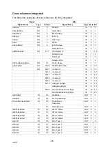
This section describes examples of IO configurations, process definitions and cross
references and is ment to be used for reference and as examples.

IO configuration

Unit type

Name = ESAB_W82_Integrated

Name = ESAB_W82_Anybus

Unit

Name = ESAB_W82

IO

Name = typeXxxxYyyy

Description of signal naming convention (if more than 1 robot a prefix is added 
explaining which robot the signal belongs to).

Type:

S

di = Digital input

S

do = Digital output

S

gi = group input

S

go = group output

S

ai = analog input

S

ao = analog output

Xxxx:

S

Signal description

Yyyy:

S

Signal action

SignalLabel = <Description>

Category = “ArcWelding”

Summary of Contents for ESAB W82

Page 1: ...0740 800 220 20130308 ESAB ABB Robot integration Interface W82 Integrated and W82 Anybus Integration manual ...

Page 2: ...BUS 9 Fieldbus connection 9 W82 DeviceNet 10 DeviceNet network 10 Tap for DeviceNet at Weld Data Unit 11 Termination 11 Position of SW1 on the welding data board 24AP1 12 24AP4 Fieldbus board DeviceNet 13 Fieldbus connector 13 Configuration 14 Baud rate 14 Node address Mac ID 14 LED indicators 15 INSTALLATION OF HARDWARE 16 Regarding U82 16 Installing W82 16 CONFIGURATION EXAMPLE 20 IO configurati...

Page 3: ...cument see page 33 This manual contains details of design changes that have been made up to and including March 2013 HOW TO USE THIS MANUAL This manual describes two different interfaces W82 Integrated and W82 Anybus Only read and use the information applicable for your chosen interface DOCUMENTATION OVERVIEW The documentation structure This manual is the ESAB ABB integration manual Delivered in t...

Page 4: ...electronic unit Feed Control Box 3004HW For robots with traditional upper arms it is recommended to use wire feed system RoboFeed 3004W RoboFeed 3004W contains both a mechanical drive unit and electronics Interface unit W82 The interface unit is installed between a welding equipment and an automation equipment such as robots The W82 is available in several versions This manual describes the follow...

Page 5: ...S0740 800 220 E20130308 P34 ESAB AB 2013 5 cr09_00 Schematic system design W82 Integrated version ESAT vis LAN ESAT via LAN W82 Anybus version ESAT via LAN Termination 120 ohm ss ...

Page 6: ... O units and automation equipment in industrial automation DeviceNet communication link is based on a broadcast oriented communication protocol the Controller Area Network CAN This protocol has I O response and high reliability even for demanding applications for example control of brakes Network connection To secure a reliable communication on the bus the drop lines are restricted in the DeviceNe...

Page 7: ... should be connected between CAN_H and CAN_L on the bus Midpoint is connected to 0V for the internal CAN bus 0V_CAN_ext for the external CAN bus via a 47nF capacitor Terminating resistors are included in the W82 They can be connected disconnected by the switches SW1 and SW2 Both the external CAN bus and the internal CAN bus have terminating resistors mounted Note When external termination of the b...

Page 8: ...S0740 800 220 E20130308 P34 ESAB AB 2013 8 cr09_01 Location of SW1 and SW2 on the welding data board 24AP1 SW1 SW2 ...

Page 9: ...740 800 220 E20130308 P34 ESAB AB 2013 9 cr09_01_1 W82 ANYBUS External fieldbus connection via DeviceNet CANopen or Profibus DP W82 fieldbus version Fieldbus connection External fieldbus connection to W82 ...

Page 10: ...e Controller Area Network CAN This protocol has I O response and a high reliability even for demanding applications for example control of brakes Network connection To secure a reliable communication on the bus the drop lines are restricted in the DeviceNet standard to a maximum length of 6 metres 20 ft Note Correct termination of the bus is essential for a reliable communication DeviceNet network...

Page 11: ... bus 0V_CAN_ext for the external CAN bus via 47nF capacitors Terminating resistors are included in the W82 They can be connected disconnected by switch SW1 Only the internal CAN bus has terminating resistors mounted Note When the W82 is is located as the last node in the internal bus network use termination on the CAN bus S Set termination switch SW1 to position ON The CAN bus will be terminated w...

Page 12: ... 12 cr09_01_2 Position of SW1 on the welding data board 24AP1 SW1 ...

Page 13: ...ix type Connector pin Signal Description 1 V Negative supply voltage 2 CAN_L CAN_L bus line 3 SHIELD Cable shield 4 CAN_H CAN_H bus line 5 V Positive supply voltage The bus interface shall be supplied with 24VDC but will operate as intended as long as the supply voltage is within the DeviceNet allowed 11 to 25V DC range ...

Page 14: ...in ON or Closed position the node interprets it as a logic 1 Baud rate There are three different baud rates for DeviceNet S 125 kbit s S 250 kbit s S 500 kbit s DIP switches 1 and 2 are used for baud rate setting Baud rate bits s Sw 1 Sw 2 125k OFF OFF 250k OFF ON 500k ON OFF Reserved ON ON Node address Mac ID Switches 3 to 8 are used to set the node address 0 63 Switch 3 is the MSB and switch 8 i...

Page 15: ... Connection timeout LED 3 Module status Colour Frequency Description Off No power to device Green Steady on Device operational Green Flashing Data size bigger than configured Red Steady on Unrecoverable fault Red Flashing Minor fault Watchdog LED The fieldbus board includes a bi colour watchdog LED indicating the status of the module Colour Frequency Indication Red Unspecified internal error or ru...

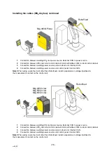
Page 16: ...with the power source Installing W82 Connections and control devices W82 Integrated W82 Anybus 1 Indicating lamp Orange indicating lamp Overheating 2 Fieldbus Connection for communication with robot system 3 Measure Connection for measurement cable for arc voltage feedback and emergency stop signal measurement kit 4 Internal CAN Connections for communication with ESAB wire feed unit and control pa...

Page 17: ...ing the gas tube S Place the interface box onto the welding power source S Fasten interface box with the two screws Installing the wire feeder and control unit Mount the feeder unit and controller according to the mounting instruction that comes in the same box as the units Power source Unpack and install the power source according to the user manual Installing the welding gun Unpack and install t...

Page 18: ...ing a wire feed unit other than RoboFeed install a separate arc voltage feedback to the measurement contact on the control unit Installing the cables W82 Anybus RoboFeed Mig 5000i iw 1 Connection between welding W82 and power source External CAN to power source 2 Connection between W82 and robot control cabinet External fieldbus CAN to robot control cabinet 3 Connection between welding power sourc...

Page 19: ...eed unit other than RoboFeed install a separate arc voltage feedback to the measurement contact on the control unit Mig 4002 c cw Mig 5002 c cw Mig 6502 c cw RoboFeed 1 3 2 4 1 Connection between welding W82 and power source External CAN to power source 2 Connection between W82 and robot control cabinet External fieldbus CAN to robot control cabinet 3 Connection between welding power source and wi...

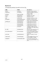
Page 20: ...e ESAB_W82_Integrated Name ESAB_W82_Anybus Unit Name ESAB_W82 IO Name typeXxxxYyyy Description of signal naming convention if more than 1 robot a prefix is added explaining which robot the signal belongs to Type S di Digital input S do Digital output S gi group input S go group output S ai analog input S ao analog output Xxxx S Signal description Yyyy S Signal action SignalLabel Description Catego...

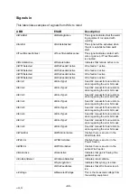
Page 21: ...eFeeder1On Enable Disable wire feeder 1 doWireFeeder2On Enable Disable wire feeder 2 doWireFeeder3On Enable Disable wire feeder 3 doWireFeeder4On Enable Disable wire feeder 4 doAnalogOn Wirefeed Voltage reference controlled from FP instead of weld data number Rel_Wire doReleaseWireOn Execute a current pulse to burn of the wire if frozen in weld pole doTouchSenseActive doTouchSenseOn Turns on the p...

Page 22: ...r3 diErrorType3 See U82 manual for future inform ation regarding the error bit mask diError4 diErrorType4 See U82 manual for future inform ation regarding the error bit mask diError5 diErrorType5 See U82 manual for future inform ation regarding the error bit mask diError6 diErrorType6 See U82 manual for future inform ation regarding the error bit mask diError7 diErrorType7 See U82 manual for futur...

Page 23: ...ding equipment giWeldDataNumber This is updated every time there has been a successful recall of a weld data set aiWeldVoltageRef This value indicates which voltage the welding machine is using aiWireFeedSpeedRef This value indicates which wire feed speed the welding machine is using aiSynergicVoltage This value indicates the result of the calculations done by the weld ing equip ...

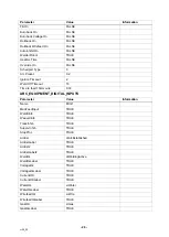
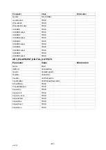
Page 24: ...Units SI_UNITS Restart On TRUE Restart Distance 5 Number of retries 3 Scrape On TRUE Scrape Optional On TRUE Scrape Width 3 Scrape Direction 90 Scrape Cycle Time 0 2 Ignition Move delay On FALSE Motion Timeout 3 Weave Sync On TRUE ARC_ROBOT_PROPERTIES Parameter Value Information Name ARC1_T_ROB1 Units SI_UNITS Restart On TRUE Restart Distance 5 Number of Retries 3 Scrape On TRUE Scrape Optional On...

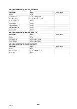
Page 25: ...er Value Information Name ARC1_EQUIP_T_ROB1 Welder Type StandardIO Loaded in Robot T_ROB1 Use Arc Equipment Class stdIO_T_ROB1 Use Arc Equipment Properties MIG1 ARC_EQUIPMENT_CLASS Parameter Value Information Name stdIO_T_ROB1 Equipment Class File Name awEquipSTD Path RELEASE options arc WeldEquip Code ARC_EQUIPMENT_PROPERTIES Parameter Value Information Name MIG1 Use Arc Equipment IO DI MIG1 Use ...

Page 26: ...meout 10 Time to feed 15mm wire 0 33 ARC_EQUIPMENT_DIGITAL_INPUTS Parameter Value Information Name MIG1 ManFeedInput TRUE WeldInhib TRUE WeaveInhib TRUE TrackInhib TRUE SupervInhib TRUE StopProc TRUE ArcEst diArcEstablished ArcEstLabel TRUE ArcEst2 TRUE ArcEstLabel2 TRUE WeldOk diWeldingActive WeldOkLabel TRUE VoltageOk TRUE VoltageOkLabel TRUE CurrentOK TRUE CurrentOKLabel TRUE WaterOk siWater Wa...

Page 27: ...3Label TRUE USERIO4 TRUE USERIO4Label TRUE USERIO5 TRUE USERIO5Label TRUE ARC_EQUIPMENT_DIGITAL_OUTPUTS Parameter Value Information Name MIG1 AWError doQuickStop GasOn doGasPurgeOn WeldOn doWeldOn FeedOn doWireFeedOn FeedOnBwd doWireFeedReverseOn SchedStrobe TRUE ProcessStopped TRUE SupervArc TRUE SupervVolt TRUE SupervCurrent TRUE SupervWater TRUE SupervGas TRUE SupervFeed TRUE SupervGun TRUE ...

Page 28: ...edRef CurrentReference TRUE ControlPort TRUE VoltReference2 TRUE FeedReference2 TRUE ControlPort2 TRUE ARC_EQUIPMENT_ANALOG_INPUTS Parameter Value Information Name MIG1 VoltageMeas aiMeasuredVoltage CurrentMeas aiMeasuredCurrent ARC_EQUIPMENT_GROUP_OUTPUTS Parameter Value Information Name MIG1 SchedulePort goWeldDataNumber ModePort TRUE ...

Page 29: ...Number IN 2 0 7 GO 24 31 reserved IN 3 0 7 32 39 reserved IN 4 0 7 40 47 reserved IN 5 0 7 48 55 reserved IN 6 0 7 56 63 reserved IN 7 0 7 64 79 Voltage Low Byte IN 8 0 7 Voltage High Byte IN 9 0 7 80 95 Wire Feed Speed Low Byte IN 10 0 7 Wire Feed Speed High Byte IN 11 0 7 diWeldEst DI 49 Weld Busy OUT 0 0 diArcEst DI 48 Arc Acknowledge OUT 0 1 diTouchSenseContact DI 50 TouchSense Response OUT 0 ...

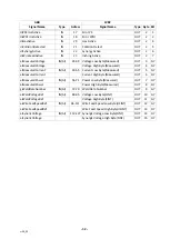
Page 30: ...ive OUT 2 6 0 Inching Active OUT 2 7 aiVoltage AI 0 7 Voltage Low Byte Measured OUT 3 0 7 8 15 Voltage High Byte Measured OUT 4 0 7 aiCurrent AI 16 23 Current Low Byte Measured OUT 5 0 7 24 31 Current High Byte Measured OUT 6 0 7 aiPower AI 32 39 Power Low Byte Measured OUT 7 0 7 40 47 Power High Byte Measured OUT 8 0 7 Weld Data Number OUT 9 0 7 Voltage Low Byte SINT OUT 10 0 7 Voltage High Byte ...

Page 31: ... Weld Data Number IN 2 0 7 aoWeldVoltageRef OUT AO 64 79 Voltage Low Byte IN 8 0 7 aoWeldVoltageRef Voltage High Byte IN 9 0 7 aoWireFeedSpeedRef OUT AO 80 95 Wire Feed Speed Low Byte IN 10 0 7 aoWireFeedSpeedRef Wire Feed Speed High Byte IN 11 0 7 diWeldingActive IN 0 Weld Busy OUT 0 0 diArcEstablished IN 1 Arc Acknowledge OUT 0 1 diTouchSenseResponse IN 2 TouchSense Response OUT 0 2 diRemoteActi...

Page 32: ...Current IN AI 40 55 Current Low Byte Measured OUT 5 0 7 aiMeasuredCurrent Current High Byte Measured OUT 6 0 7 aiMeasuredPower IN AI 56 71 Power Low Byte Measured OUT 7 0 7 aiMeasuredPower Power High Byte Measured OUT 8 0 7 giWeldDataNumber IN GI 72 79 Weld Data Number OUT 9 0 7 aiWeldVoltageRef IN AI 80 95 Voltage Low Byte SINT OUT 10 0 7 aiWeldVoltageRef Voltage High Byte SINT OUT 11 0 7 aiWireF...

Page 33: ...nductive materials e g fabrics or insulators e g plastics generate and hold static charge so you should not bring unnecessary nonconductive items into the work area It is obviously difficult to avoid all such items so various means are used to drain off any static discharge from persons to prevent the risk of ESD damage This is done by simple devices wrist straps connected to ground and conductive...

Page 34: ...l 34 91 878 3600 Fax 34 91 802 3461 SWEDEN ESAB Sverige AB Gothenburg Tel 46 31 50 95 00 Fax 46 31 50 92 22 ESAB international AB Gothenburg Tel 46 31 50 90 00 Fax 46 31 50 93 60 SWITZERLAND ESAB AG Dietikon Tel 41 1 741 25 25 Fax 41 1 740 30 55 UKRAINE ESAB Ukraine LLC Kiev Tel 38 044 501 23 24 Fax 38 044 575 21 88 North and South America ARGENTINA CONARCO Buenos Aires Tel 54 11 4 753 4039 Fax 54...

Reviews: