background image

103

The arrows enable scrolling in each menù, the enter enables confirming the menù item choice, the

Menù pushbutton enables to return to the higher level selection.

The HMI is connected to the electronics on board the circuit-breaker by means of two bushing

conductors using the plug socket of the circuitbreaker itself.

The HMI has a universal power supply and it can be supplied with direct voltages from 24 to 250

Vdc or with alternating voltages at 50 and 60 Hz from 24 to 240 Vac.

Fig. 97

Summary of Contents for eVM1

Page 1: ...eVM1 Installation and service instructions 12 17 5 kV 630 1250 A 16 31 5 kA ...

Page 2: ...1 ...

Page 3: ... manual Check that the rated performance of the apparatus is not exceeded during service Check that the personnel operating the apparatus have this instruction manual to hand as well as the necessary information for correct intervention Pay special attention to the notes indicated in the manual A note contains additional information worth noting in the specific context and looks like the following...

Page 4: ... 2 General characteristics of circuit breakers for UniGear type ZS1 switchgear and PowerCube modules 18 8 3 Control circuit power supply 19 8 4 Standard fittings 20 8 5 Optional accessories 21 9 Installation 23 9 1 General 23 9 2 Trip curves 23 9 3 Preliminary operations 24 9 4 Installation of fixed circuit breaker 24 9 5 Installation of withdrawable circuit breaker 24 9 6 Auxiliary circuits 24 9 ...

Page 5: ...Toolbar andTabs 36 14 5 General settings 41 14 6 Logic Configuration 58 14 7 Protection Parameters 62 14 8 Input Output Mapping 88 14 9 Monitoring 94 14 10 Communication 96 14 11 Password 102 14 12 LCD Panel HMI 102 14 13 Local CB HMI 104 14 14 Anomaly list 105 14 15 Procedure for discharging the capacitor 106 14 16 Insulation Test on CB secondary wiring 107 ...

Page 6: ...ams assembly and installation drawings any protection coordina tion studies etc especially regarding any variants requested in relation to the standardised configurations Only use original spare parts for maintenance operations For further information please also see the technical catalogue of the circuit breaker All the installation putting into service running and maintenance operations must be ...

Page 7: ...onfirmation sent by ABB Caption A Circuit breaker rating plate B Drive rating plate 1 Type of apparatus 2 Symbols of compliance with Standards 3 Serial number 4 Circuit breaker characteristics 5 Characteristics of the drive auxiliaries Warning A B 3 4 2 CIRCUIT BREAKER IEC 62271 100 eVM1 CEI 17 1 CLASSIFICATIONSN SN PR YEAR M MASS kV Ur VOLTAGE A Up LIGHTING IMPULSE WITHSTAND VOLTAGE kV Ud CORRENT...

Page 8: ...case avoid any accidental impacts or positioning which stresses the structure of the appa ratus 4 Handling Before carrying out any operations always make sure that the capacitors are discharged To lift and handle the circuit breaker proceed as follows fig 2 use a special lifting tool 1 not supplied fitted with ropes with safety hooks 2 insert the hooks 2 in the supports 3 fixed to the frame of the...

Page 9: ...y extremely long useful life expectancy and for being completely maintenance free The eVM1 P type vacuum circuit breakers are available in the withdrawable version Their basic structure is shown in the Technical data section 5 1 Standards and regulations 5 1 1 Fabrication The eVM1 circuit breakers conform to the following Standards VDE 0670 part 1000 and IEC 60694 DIN VDE 0670 part 104 and IEC 622...

Page 10: ...lative humidity measured for a period longer than 24 hours must not exceed 95 The average value of the pressure of the water vapour without condensation measured for a period longer than 24 hours must not exceed 2 2 kPa The average value of the relative humidity measured for a period longer than 1 month must not exceed 90 The average value of the pressure of the water vapour measured for a period ...

Page 11: ...ontrols and instruments coupling for manual emergency operation 9 mechanical state indicator 6 mechanical operation counter 5 control panel 7 with opening and closing pushbuttons 6 1 1 Structure of the control module The control module 10 of the circuit breaker consists of a microprocessor opto electrical input couplers output relay electronic power system for controlling the actuator coils 1 Pole...

Page 12: ...g to the following criteria Case 1 circuit breaker in the open position The energy available is sufficient for one closing and opening operation Case 2 circuit breaker in the closed position The energy available is sufficient for one opening operation The energy available is sufficient for one opening operation within about 30 seconds from interruption of the auxiliary power supply If the energy s...

Page 13: ...nterrupter 4 and then through the moving contact 2a and the flexible connector 6 as far as the bottom terminal of the circuit breaker 2 The movement of the moving contact are ensured by the insulating tie rod 8 and by the kinemat ics 9 Fig 7 1 Top terminal 1a Fixed contact 2 Bottom terminal 2a Moving contact 3 Pole in resin 4 Vacuum interrupter 5 Current sensor 6 Flexible connector 7 Contact press...

Page 14: ...front Withdrawable circuit breakers of the same type and characteristics are interchangeable How ever the code of the connector prevents incorrect combinations between the circuit breaker and switchgear 7 Operation 7 1 Operation of the circuit breaker drive 7 1 1 Magnetic actuator The magnetic actuator used in the eVM1 circuit breakers generates the run required to operate the moving contacts of t...

Page 15: ...gnetic actua tor are managed by a microprocessor The power supply voltage must be applied to the AC DC converter The capacitor must be sufficiently charged for the next operation Circuit breaker position Operations Open Closes and Opens Closed Opens Magnetic latching in end of run position Magnetic latching and action of the magnetic field of a coil Moving armature in opposing position and magneti...

Page 16: ...of the control module for the opening function is designed so that an opening command is carried out directly even in the case of a fault in the microprocessor 7 1 5 Truck locking magnet The locking magnet is inserted in withdrawable circuit breakers with manual movement and pre vents traverse of the withdrawable truck when there is no power supply voltage It is also linked to the interlock betwee...

Page 17: ...rovided with devices which only allow connection and disconnection of the plug connector 1 fig 10 in the test isolation position Any detailed information regarding additional interlocks e g with the earthing switch operating mechanism is given in the specific order documentation 7 3 2 Interlocks in the case where withdrawable trucks are used UniGear ZS1 type switch gear and PowerCube modules 1 The...

Page 18: ...Ir A Isc kA Ik kA Ip kA O 0 3s CO 15s CO ms ms ms ms Actuator No Interrupters No At rated current No Under short circuit No H mm W mm D mm I mm A mm kg W W C IEC 61000 IEC 60255 Circuit breaker Standards Rated voltage Rated insulation voltage Withstand voltage at 50 Hz Impulse withstand voltage Rated frequency Rated normal current 40 C Rated breaking capacity rated symmetrical short circuit curren...

Page 19: ...275 205 eVM1 12 12 20 p275 1250 25 700 275 205 eVM1 12 12 25 p275 1250 31 5 700 275 205 eVM1 12 12 32 p275 17 5 630 16 450 150 205 eVM1 17 06 16 p150 630 20 450 150 205 eVM1 17 06 20 p150 630 25 450 150 205 eVM1 17 06 25 p150 630 31 5 450 150 205 eVM1 17 06 32 p150 1250 16 450 150 205 eVM1 17 12 16 p150 1250 20 450 150 205 eVM1 17 12 20 p150 1250 25 450 150 205 eVM1 17 12 25 p150 1250 31 5 450 150...

Page 20: ...ters No At rated current No Under short circuit No H mm L mm P mm I mm A mm kg W W C IEC 61000 IEC 60255 Circuit breaker Standards Rated voltage Rated insulation voltage Withstand voltage at 50 Hz Impulse withstand voltage Rated frequency Rated normal current 40 C Rated breaking capacity rated symmetrical short circuit current Rated short time withstand current 3 s Making capacity Operation sequen...

Page 21: ...1 P 17 12 20 p150 1250 25 450 150 205 35 eVM1 P 17 12 25 p150 1250 31 5 450 150 205 35 eVM1 P 17 12 32 p150 Notes L Width of circuit breaker I Horizontal poles center lines A Upper and lower distance ø Diameter of the isolating contact 8 3 Control circuit power supply The energy for circuit breaker operation is supplied by one or more capacitors which are kept charged by a feeder which also sees t...

Page 22: ...assign all the application meanings of the circuit breaker please refer to the 1VCD400060 sche matic drawings Among the fixed inputs which cannot be programmed are input for the undervoltage function remote opening and closing commands disabling the opening operation circuit breaker in service circuit breaker under test hardware only second opening of the circuit breaker for maximum reliability Am...

Page 23: ...protection of the electronic power circuit with auto shut down of the feeder in the case of overtemperature and or overcurrent control of opening and closing coil continuity watchdog DO16 8 5 Optional accessories The accessories identified with the same number are alternative to each other 1 Interface for panel HMI The interface allows the control and protection device incorporated in the eVM1 cir...

Page 24: ... configuring the eVM1 when there is no HMI see para 14 10 Kit which makes it possible to have an RS485 port in the low voltage compartment of the panel to connect the personal computer to in those cases where there is no HMI 6 eVM1 RS232 USB RS485 configuration cable see para 14 10 Cable which allows the personal computer to be connected to the RS485 port prepared in the low voltage compartment of...

Page 25: ...ions must be carefully studied and followed It is good practice to use gloves to handle the pieces during installation The areas involved by the passage of power conductors or conductors of auxiliary cir cuits must be protected against access of any animals which might cause damage or disservices 9 2 Trip curves The following graphs show the number of clos ing opening cycles No allowed of the vacu...

Page 26: ...nti clockwise for racking out until the end of run positions are reached Circuit breaker racking in out must be carried out gradually to avoid shocks which may deform the mechanical interlocks and the end of runs The torque normally required to carry out racking in and racking out is 25 Nm This value must not be exceeded If operations are prevented or difficult do not force them and check that the...

Page 27: ...25 2 1 Max 25 Nm Racking in Racking out Fig 13 Fig 14 9 7 Overall dimensions Fixed circuit breaker eVM1 p150 Ur 12 kV 17 5 kV Ir 630 A 1250 A Isc 16 kA 20 kA 25 kA 31 5 kA ...

Page 28: ...26 Fixed circuit breaker eVM1 p210 Ur 12 kV 17 5 kV Ir 630 A 1250 A Isc 16 kA 20 kA 25 kA 31 5 kA Fixed circuit breaker eVM1 p275 Ur 12 kV 17 5 kV Ir 630 A 1250 A Isc 16 kA 20 kA 25 kA 31 5 kA ...

Page 29: ...27 HMI Panel interface for eVM1 Door drilling Withdrawable circuit breaker eVM1 P p150 Ur 12 kV 17 5 kV Ir 630 A 1250 A Isc 16 kA 20 kA 25 kA 31 5 kA ...

Page 30: ... relative input or locally by pressing the I pushbutton on the front of the circuit breaker or on the panel HMI 10 2 2 Closing in the case of a power failure Closing is not advisable and is not possible 10 2 3 Opening This can be carried out remotely by applying voltage to the relative input or locally by pressing the O pushbutton on the front of the circuit breaker or on the panel HMI fig 16 10 2...

Page 31: ... must be disconnected to the protection and control unit connector XB24 and to the power supply connection protected by a 275V common mode varistor connector XB24 both on the mother card of the protection and control unit If the communication connection to the control and protection unit is made using connector D Sub 9 pin for DIN rail in a secondary compartment disconnect this connection Check th...

Page 32: ...nly be carried out by trained personnel who respect all the safety regulations Furthermore is recommended that ABB service personnel should be called in at least to check the service performances and for any repair work During maintenance work turn the power supply off and put the apparatus under safe conditions Before carrying out any operations make sure that the circuit breaker is open the capa...

Page 33: ... from this instruction manual see par 14 15 11 1 3 Drive with magnetic actuator The drive with magnetic actuator is maintenance free up to the number of operation cycles indi cated in paragraph 11 1 1 11 2 Inspections and functional tests 11 2 1 Interruption devices in general Carry out regular inspections to check that the interruption devices are in good condition Inspection at fixed intervals c...

Page 34: ...ed has been exceeded or during maintenance operations Before carrying out the functional test open the circuit breaker and take it to the test position withdrawable circuit breaker or insulate and block the working area and make it safe in conformity with the safety rules and according to the regulations in force fixed circuit breakers follow the procedure for discharging the capacitor carry out a...

Page 35: ...of vacuum of the interrupter of the circuit breaker poles turn the power supply off and make the working area safe by following the safety regulations specified in the IEC DIN VDE Standards open the circuit breaker earth a terminal of each circuit breaker pole connect the earth terminal of the VIDAR tester to the circuit breaker structure connect the high voltage terminal of the VIDAR tester to th...

Page 36: ...t be carried out following the in structions enclosed with the spare parts by ABB personnel or by suitably qualified cus tomer personnel with in depth knowledge of the apparatus IEC 60694 and all the Stand ards aimed at carrying out these interventions in safe conditions Should the maintenance be carried out by the customer s personnel responsibility for the interventions remains with the customer...

Page 37: ...on of this control mode requires caution because operations are allowed both from the HMI and remotely 14 3 Acronyms and definitions 14 3 1 Acronyms CB Circuit breaker or Switch CCT Cable Current Transformer CP Control Panel CU Control Unit CT Current Transformer CoT Configuration Tool HMI Human Machine Interface 14 3 2 Definitions Active signal A signal is active when high e g logic value 1 or ov...

Page 38: ... functions are detailed in the Chapter Transfer 14 4 2 Menu The Menu function lists are only fully accessible with service level rights see chapter Password Otherwise some functions are disabled and coloured in light grey 14 4 2 1 File The File Menu provides utilities for file management New opens a new unnamed project with all data as default configuration Open opens a previously saved project re...

Page 39: ...MI Upload function Transfers the configuration file from the electronic device IED to the PC if an active connection is available The file can be renamed and stored on disk for download onto a new CB to be used as a replacement or spare Information relevant to Product serial numbers and Product License are linked to the specific IED and will not be copied Download function Transfers the configurat...

Page 40: ...lable at Configuration Tool opening This menu allows two choices Fig 21 Fig 21a Reset Values Only set all the parameter of the selected default configuration Reset Values and Store to eVM1 set all the parameter of the selected default configurationand transfers this configuration from PC to the electronic device IED if an active connectionis available HW SW Versions reads the HW and SW versions fr...

Page 41: ...ass and to improve overall analog input acquisition precision Start Secondary Calibration with a pop up window this function executed at IED production and accessible only to service personnel provides the possibility of calibrating the IED analog channels by injecting a reference signal Refer to calibration and test procedure document 1VCD6000132 Primary Calibration Factors the calibration factor...

Page 42: ... panel will not light up Select Firmware Download from CoT browse for file launch with Open in browse window On completion of updating the firmware version exit and re launch the configuration tool power down the IED and reconfigure it to half duplex removing JP6 and put I1 dip switches in off position or according to required functionalities Fig 24 Whole Calibration Factors with a pop up window t...

Page 43: ... and is not modified by new configuration or firmware download Read retrieves data from the IED for compatibility check and information to ABB service Available when an active communication link has been established with the IED CB Closing Counter opens a window that shows the number of closing operations performed by the CB and the percentage of contact wear due to load or short circuit opening o...

Page 44: ... Network Frequency value by default 50 Hz 14 5 General Settings The General Settings Tab enables you to configure the HW according to the Electronic Device IED integrated in the CB and to the application characteristics such as the current ratings network frequency and single line diagram It manages enabling of a number of automation functions Do not make any changes to the eVM1 configuration unle...

Page 45: ...mer must be connected in the primary circuit This option should be used in networks with high resistance compensated or isolated neutral point where low amplitude earth fault currents occur to provide higher sensitivity The CCT Earth Nominal Primary Current is the residual current transformer rated current Ine 1 A A The earth fault protection function setting range is adjusted automatically accord...

Page 46: ...nd outputs DI O are mapped according to selected predefined meanings see chapter Input Output Mapping Refer to schematic drawings 1VCD400060 for complete meaning assignment of withdrawable CB application In this case all I O are assigned and are not user configurable By ticking the free scheme all available meanings can be assigned to the configurable I O with no restrictions As default the free D...

Page 47: ...tion It shows the panel single line diagram according to the selection and available inputs When LCD Panel HMI is selected the Local Remote selection Key and Close Open commands from local functions are provided by the HMI and the meanings are not configurable in the DI mapping Tab see picture below Trip Signal and Anomaly Reset function can still be performed both from HMI with the Reset pushbutt...

Page 48: ...unctions are not ticked i e inactive by default In the example figure above the UnderVoltage function is enabled 14 5 5 1 ANSI Re close This activates the Re Close Function according to ANSI requirements see figure This function is only activated when the CB is in the closed position and a Close Command is valid positive edge event Close and Open can be local or remote commands If the close comman...

Page 49: ...lose it is necessary to activate the close remote close input Vice versa it takes place from Remote to Local mode transition remote stored closing positive edge is reset CASE1 normal re close sequence performed locally by pushbuttons CASE2 when the close pushbutton is pressed the ED is ready for a re closing operation CB closed local When the Loc Rem mode input is switched to remote mode the previ...

Page 50: ...l default DI 13 and from Remote Open Command from remote default DI3 or from Communication Use CB Open Disabling function with caution as all Open Commands apart from 2nd Safety Open including those issued from protections will be not executed This condition might result in malfunction of protection functions The Second Safety Open is not blocked by this function and will be executed 14 5 5 2 CB O...

Page 51: ... CB Open Disabling is not active i e it is at high level 1 b DSP fails and the WD signal enables the HW block the Second Safety Command is executed as a HW opening if dip switch I1 S1 is closed ON AND dip switch I1 S2 is open OFF OR dip switch I1 S2 is closed ON and DI 4 CB Open Disabling is not active i e it is at high level 1 14 5 5 5 1 HW configuration The Second Safety Open operating mode is s...

Page 52: ...he IED An Anomaly alarm is issued and the No Anomaly LED on the CB HMI goes ON The system is in Energy Failure status when the capacitor charge is under the Othreshold KO level The following behaviour is allowed CB position Closed Open Capacitor Charge Energy sufficient for O CO operations Opening allowed Closing allowed Energy sufficient for CO operations Opening allowed Closing allowed Energy su...

Page 53: ...d An Anomaly alarm is issued and the No Anomaly LED on the CB HMI goes ON The UV function will come back in passive status and Reset if the voltage on DI1 exceeds 0 85 of the dip switch value setting 14 5 5 7 1 SW configuration Under Voltage Condition 0 35 Vn 0 7 Vn 0 85 Vn Vn Voltage V Reset Detected CB Close not allowerd CB Open allowerd CB Open not allowerd CB Close allowerd The UnderVoltage Op...

Page 54: ...rformed In both cases Close block enabled or disabled during UnderVoltage timing opening commands via control panel pushbuttons or external inputs will be performed normally If the UnderVoltage Close block is disabled Closing Allowed is enabled and the voltage on the relative external UV input is absent the CB can be closed the function timing will start again when microprocessor reads the CB clos...

Page 55: ...c A typical example is a re closure sequence e g O 0 3s CO 3s CO 15s CO on an overhead line where transient faults may occur and be cleared by sequence 14 5 5 9 Trip in case of current overflow The IED monitors the currents up to 25 times the Nominal Primary Current value entered in the General Settings In The protection setting range is limited to 20 times In Therefore under fault conditions the ...

Page 56: ... maximum charge level until there is enough energy for an opening or closing operation 14 5 6 2 Actuator Coil Supervision The IED monitors the actuator opening and closing coil continuity It verifies that both coils are connected and not interrupted they are both not in open circuit condition When this condition is true the Coil OK LED on the CB HMI goes ON When the function becomes false an Anoma...

Page 57: ... opening is performed when either Close or Open operation is not completed the CB does not reach the desired position at the maximum time Tmax of 70ms 1 CB remains in initial position for Open operation only 2 CB reaches a wrong intermediate position 3 CB touches the final position but bounces into a wrong intermediate position If the Auto trip opening command is carried out properly the IED will ...

Page 58: ...o not increase the counter This function preserves the IED components and obliges the operator to check the circuit breaker 14 5 6 6 Trip Free Function Trip Free 2 is the capability of the CB to have the moving contacts return to and remain in the open position when the opening operation is initiated after the closing operation is started even if the closing force and command are maintained To ens...

Page 59: ...pening signal is already running See figure below C Time Close Command Open Command CB Status O CB Status Close Command Open Command c o CommandValid Command Valid In correspondence with release of the Open command if the Close signal is still high the CB will not be closed because the Close command is only considered valid on positive edge front If the closing operation is initiated and in the me...

Page 60: ...nables management of the logical output Start and Trip signals of the protection function and use of external signals to block them 14 6 1 1 Protection Logic Input Signals Enable Each protection function is independently activated ENABLED in the Protection Parameters dialogue window when the protection box is ticked When a Protection Function is not enabled the corresponding Start and Trip outputs...

Page 61: ...released does the protection become active and if the start conditions are true begins to count After the block release the set protection time delay has to expire before the protection trips BLOCK from Motor Start protection Each active protection function can be blocked by the Motor Start protection in the Motor Start configuration pop up window The active protections have a selectable box When ...

Page 62: ... below Interlocking Input 1 is used to block all overcurrrent protections while Interlocking Input 2 is used to block all earth fault protections 14 6 1 2 Protection Logic Output Signals Each protection of the Start and Trip logical outputs are only active when the function is in Start or Trip status respectively By combining Start and Trip logical outputs from Protection Functions the general Sta...

Page 63: ...ed Re closing of the CB is not allowed until Reset see Close allowed in Trip status for exceptions If no Reset means are available pushing the local CB HMI opening pushbutton for 5s resets the trip signal Remember that a re close on network faulty condition is then possible Interlock Output 1 and 2 Interlock Output 1 and Interlock Output 2 are Start signals and all enabled protection function can ...

Page 64: ...n sets are available the basic set provides various types of phase overcurrent and earth fault overcurrent and the full set adds motor protection functions All protection functions are according to IEC 60255 3 and IEC 60255 8 Standards Name Basic set Full set 51 Overcurrent IDMT NI VI EI LI Yes Yes 50 Overcurrent DT1 Yes Yes 50 Overcurrent DT2 Yes Yes 51N Earth fault IDMT Yes Yes 50N Earth fault D...

Page 65: ...63 Available protection functions can be independently activated in the Protection Parameters dialogue window by ticking the relative box Fig 54 Fig 55 ...

Page 66: ...ection Machine State The machine state for a generic protection is shown in the figure below C Protection activated A Reset all the protection variabels C Protection activated C1 C9 A C Start detected A Start protection counter A Set the output start C Trip initiated C6 A Set protection tripping state C Trip C7 A C Start persistent C4 C5 A Wait protection counter to expire C Start reset C3 A Reset...

Page 67: ...rent Protection Two overcurrent definite time protection functions are available Each of them can be activated independently Overcurrent definite time low setting DT1 I Overcurrent definite time high setting DT2 I 14 7 2 1 1 Parameters Start Value I Current threshold for overcurrent condition detection Time t Time delay for overcurrent Trip condition detection Parameter Values Default Step Unit Ex...

Page 68: ...ssive status and the start signal will be cleared if the current falls below 95 of the setting threshold value for all the phases After the protection has entered the start status and the preset operating time Time has elapsed the function goes into TRIP status and the trip signal is generated The protection function will exit the TRIP status the trip signal and the counter will be cleared when th...

Page 69: ...shold setting range is expressed in primary current Ampere A up to 2 40 In where In is the Nominal Primary Current value entered in the General Settings 14 7 2 2 2 Operation criteria If the measured RMS current exceeds the setting threshold value Base current Ieb by a factor of 1 2 for at least one phase then the protection function is started The protection function will remain in START status un...

Page 70: ...acteristic The formulas for the trip time according to British Standard BS 142 and IEC 60255 3 are reported in the chapter IDMT Protection Time Current Characteristics The protection function will exit the TRIP status the trip signal and the counter will be cleared when the measured current value for all the phases falls below 40 of the setting threshold value The overcurrent time step characteris...

Page 71: ...tection functions evaluate the RMS residual current at the fundamental frequency in two ways direct measurement of earth fault current at the dedicated analog input via an external residual current transformer the lowest Start Value setting allowed is 0 05 Ien as the protection is more sensitive or neutral current calculated by the vectorial sum of the three phase currents Ticking the CCT presence...

Page 72: ... according to British Standard BS 142 when the time multiplier k is used When the time multiplier k is set to one k 1 the IDMT curve is in accordance to IEC 60255 3 Parameter Values Default Step Unit ExplanationType Type NI VI EI LTI NI Tripping curve Base Current Ieb 0 30 2 40 p u di Ien 2 Ien 1 A Current threshold Time Multiplier K 0 05 1 50 1 0 05 Time multiplier BS 142 The threshold setting ra...

Page 73: ...d value When the protection enters the start status the operating time is continuously recalculated according to the set parameters and earth fault current value If the calculated operating time is exceeded the function goes into TRIP status and the trip signal becomes active The operating time depends on the measured current and the selected current time characteristic The formulas for the trip t...

Page 74: ...e current Ieb 14 7 2 5 2 Earth fault IDMT Earth fault IDMT function evaluates the measured or calculated RMS amount of residual current at the fundamental frequency It will be activated when measured or calculated earth current start conditions are true earth current value is above 1 2 times the setting threshold value Base current Ieb When setting the base current parameter Ieb take care not to e...

Page 75: ... 2 0 80 0 80 0 Long time inverse 1 0 120 0 120 0 The formula is implemented in accordance with BS 142 and the k factor ranges from of 0 05 to 1 50 When the time multiplier k in the parameters dialogue window is set to one k 1 the IDMT protections operate in accordance with IEC 60255 3 The tripping characteristics of the four different IDMT curves are shown in the following figures According to the...

Page 76: ...74 Fig 66 Fig 67 ...

Page 77: ...75 Fig 68 Fig 69 ...

Page 78: ... the motor from speeding up If this malfunction occurs the starting current would flow permanently and the motor would be thermally overloaded The protection operates like an Overcurrent Protection function Nominal Motor Current IMn Nominal Motor current Start Value Is Current threshold for motor start condition detection Time tbr Time delay for Trip condition detection Parameter Values Default St...

Page 79: ...otor Start protection function A tachometer generator or a speed switch is used to send a defined signal at a specified speed If the rotor of the monitored motor is blocked the missing speed signal will ensure that the overcurrent function in the protective function continues to remain active 14 7 3 2 Thermal Overload Protection In motor protection applications the thermal overload protection is o...

Page 80: ...ializing Parameter Values Default Step Unit ExplanationType Nominal Motor Current IMn 0 5 1 2 p u di In 50 1 A Nominal Motor Current Nominal Motor Temperature TMn 50 400 50 1 C OperatingTemp atTenv and IMn Time Constant Off I 0 1 IMn 10 60000 10 1 s Cooling constant Time Constant Normal 10 20000 10 1 s Working heating constant Time Constant Overheat I 2IMn 10 20000 10 1 s Overheating constant Warn...

Page 81: ... threshold value Twarn The protection function will exit theTRIP status and the trip signal will be cleared when the estimated temperature falls below the setting threshold value Ttrip The protection function also prevents reconnection after a trip of overheated machines until the estimated motor temperature has fallen below the warning temperature Twarn according to calculated motor cooling proce...

Page 82: ...al to the squared value of current In general the value of asymptotical temperature increment when the generic current I is flowing into the motor is then given by According to the above considerations the estimated instantaneous temperature T of the motor taking into account the environment temperature and the actual motor current is calculated according to To better approximate different motor o...

Page 83: ...forTrip condition detection start energy integral I2 t Time ts Time for Trip condition detection Motor Start IMs Current threshold for motor start condition detection Parameter Values Default Step Unit Explanation Nominal Motor Current IMn 0 80 1 20 p u di In 100 1 A Motor nominal current Start Value Is 1 00 20 00 p u di IMn 100 1 A Trip condition detection integral I2 t Time ts 50 300000 50 10 ms...

Page 84: ...otor Current IMn AND b within a time of 100 ms the measured motor current exceeds the setting motor start detection Motor Start IMs When a motor start is detected the protection is started the start signal is activated and the current time integral is calculated dt t i 2 The protection function will return to passive status and the start signal will be cleared if the maximum motor current falls be...

Page 85: ... T rst has elapsed the counted number of starts is decreased by one If the preset number of warm or cold respectively starts is reached the start signal of the protection function is activated If there is another start the protection function trips Number of Starts N of cold starts below temperature thresholdTws declared by the Motor manufacturer Number of Warm Starts Nws N of warm starts above te...

Page 86: ...warm or cold start the relative counter is incremented by one unit With every warm start both the warm counter and the cold counter are incremented If no start has occurred after the set time interval Reset Time t rst it is assumed that the motor had time to cool down and both cold and warm start counters are decremented by one unit If the preset number of warm Number of Warm Starts Nws or respect...

Page 87: ...achines and handles situations of intermittent NPS current Start Value Is Current threshold for negative sequence condition detection Heating Parameter K Heating parameter to vary time delay for Trip condition Reset Time t rst The function remains in BLOCK status until the reset time has elapsed e g to block the possibility of re closing a motor Time Decreasing Rate Parameter to vary thermal memor...

Page 88: ...unction goes into TRIP status and the trip signal becomes active The protection function will exit the TRIP status and the trip signal will be cleared when the NPS current value falls below 40 of the setting threshold value The operating time depends on the calculated negative phase sequence as follows where t time until the protective function trips under sustained NPS overcurrent K heating param...

Page 89: ...rly decremented with time using a user configurable slope i e Time Decreasing Rate 100 means full memory 0 means no memory 14 7 3 5 4 NPS function State Machine Transition Initial Status Final Status Condition s 1 PASSIVE PASSIVE 2 PASSIVE START 3 START PASSIVE OR Reset_signal_received 4 START START AND 5 START TRIP AND TRIP t t 6 TRIP TRIP 7 TRIP BLOCK 8 BLOCK BLOCK 9 BLOCK PASSIVE OR Reset_signa...

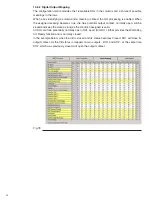
Page 90: ... and a choice of possible meanings in the rows When a box identifying a column and a meaning is ticked DI processing is enabled For standard DIs when the input signal goes High i e an AC DC voltage over the activation threshold of about 20 V is applied for at least 10 ms 20 ms for Open Commands the In the example below when DI2 goes high a CB Close command will be performed Meanings with the prefi...

Page 91: ...uire presence of Line disconnector operating rod valid when DI is high Status signal to acquire the two position cable side earth disconnector position valid when DI is high open 1 Status signal to acquire the two position cable side earth disconnector position valid when DI is high closed Status signal to acquire presence of cable side earth disconnector operating rod valid when DI is high Interl...

Page 92: ...tial output contact normally open will be closed and keep the state as long as the condition assigned is valid All DOs are free potentially normally open NO apart from DO 16 that provides the WatchDog not Ready function and is normally closed In the example below when the CB is closed and its status becomes Closed DO1 will close its output contact As the CB status is mapped on two outputs DO1 and ...

Page 93: ...ntact closes when at least one protection function associated in the Logic Configuration Tab goes into trip status Output contact to signal CB was opened due to Undervoltage function contact closes when UnderVoltage performs CB opening and stays latched until the Anomaly is reset When the CB is closed again close allowed while UV is active the BO stays closed Output contact to signal CB was opened...

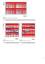
Page 94: ...esistance with contacts open Min 103 Mohm measured at 500 V Storage temperature 40 C 85 C Temperatura di stoccaggio 40 C 100 C Mechanical life 500 000 operation at 250 V 50 60 Hz 180 operation min Electrical life 50 000 operation at 6 A 277 V 50 60 Hz resistive load see curves B and C Characteristics of the control module contacts without potential The contacts without potential control module by ...

Page 95: ...Curve A Maximum power applicable V d c on resistive load Curve B Electrical life of the contacts at 250 V a c Operations Curve C Electrical life of the contacts at 24 V d c Operations Fig 80 Fig 81 Fig 82 ...

Page 96: ...ital inputs the LED is on yellow when the input signal goes High but the associated function will be executed when there is no signal and the LED is off grey E g CB Close disabling when the LED is off the CB will not execute close commands because the function is active 14 8 Monitoring The monitoring Tab enables access to the IED to monitor DI O status CB currents start trip conditions etc when an...

Page 97: ...p condition and re close the CB 14 8 4 Analog values The analog values window shows the instantaneous RMS phase and earth current measured or calculated values 14 8 5 Motor protection values The analog values window shows quantities related to motor protection functions T0 Time to Next Motor Start s motor cooling down time estimation according to the Thermal Overload protection model It is the tim...

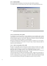
Page 98: ...onnector to the XB24 connector on the IED basic card It is possible to make the connection to the PC with a RS232 RS485 half duplex or full duplex converter or with a USB RS485 half duplex converter Enable the serial communication port of the PC by means of the Transfer Open Port menu and selection of one of the available ports among COM1 COM3 In the case where the PC has already used the addresse...

Page 99: ...5 pin connector Male of the Full Duplex D Sub 9 pin RFC 9B converter connector 1 3 2 1 5 3 8 1 XB24 connector of the basic IED card 2 Female male D Sub 9 pin adapter 3 Male USB RS485 converter 4 USB extension Male USB RS485 D Sub 9 pin adapter connector Female Male 1 1 8 2 2 1 5 5 5 Direct connection by means of the USB PC port with the IED card is available only in the Half Duplex mode Fig 85 Fig...

Page 100: ... D Sub 9 pin connector 3 RS232 RS485 half duplex converter Indirect PC connection on RS232 port IEC card by means of D Sub 9 pin connector for DIN rail in secondary compartment 3 pin connector of the Male D Sub 9 pin Female D Sub 9 pin half duplex converter RMC 9R connector connector on DIN rail 1 3 3 2 1 5 1 5 3 8 8 Indirect PC connection on USB port IEC card by means of D Sub 9 pin connector for...

Page 101: ... for DIN rail in secondary compartment Indirect connection to the IED by means of HMI RS232 IrDA converter and D Sub 9 pin connector for DIN rail in secondary compartment is available only in the Half Duplex version Female D Sub 9 pin connector Male D Sub 9 pin connector Female D Sub 9 pin HMI cable D Sub 9 pin HMI cable D Sub 9 pin connector for DIN rail for DIN rail for DIN rail 8 3 3 1 5 1 5 1 ...

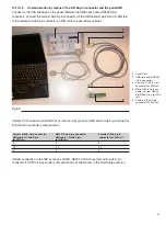
Page 102: ...o with a PC with an optional Kit Two versions are available Kit without HMI Consists of D Sub 9 pin connector for assembly on DIN rail Kit with HMI Consists of D Sub 9 pin connector for assembly on DIN rail HMI and serial connection cable Kit without HMI Consists of D Sub 9 pin connector for assembly on DIN rail Kit with HMI Consists of D Sub 9 pin connector for assembly on DIN rail HMI and serial...

Page 103: ...nal Kit every 5 eVM1 is recommended The following versions are available ABB optic cable RS232 IrDA converter and D Sub 9 pin extension RS232 485 Half Duplex converter cable male D Sub 9 pin connector USB 485 Half Duplex converter cable male D Sub 9 pin connector D Sub 9 pin interfacing adapter RS232 485 Full Duplex converter cable male D Sub 9 pin connector Fig 92 Fig 93 Fig 94 Fig 95 ...

Page 104: ...ion in service or in test position for withdrawable circuit breaker By means of a 4 position key local or remote control of the CB global control global remote or CB lock in the open position is possible Circuit breaker locked in Open position enables to use the selection key as the responsibility key for the circuit breaker A two line LCD enables direct reading of the phase and earth currents amm...

Page 105: ...her level selection The HMI is connected to the electronics on board the circuit breaker by means of two bushing conductors using the plug socket of the circuitbreaker itself The HMI has a universal power supply and it can be supplied with direct voltages from 24 to 250 Vdc or with alternating voltages at 50 and 60 Hz from 24 to 240 Vac Fig 97 ...

Page 106: ...t least one protection function is in Start condition general Start signal is active Trip LED on when at least one protection function has entered Trip condition general Trip signal is active and latched see Reset Local LED on when the IED is in Local control Mode Off when in remote or global mode Networks LEDs blinking when an active communication is established with the IED left for com municati...

Page 107: ... ABB Service with code ANOMALY CODE 1 CB anomaly Inconsistency among CB statuses Error in CB status 2 Undefined CB status 3 CB anomaly Reached max No of opening attempts Achieved max No of Opening attempts 4 IED anomaly Call ABB Service with code ANOMALY CODE 5 IED anomaly Call ABB Service with code ANOMALY CODE 6 ANOMALY CODE 7 ANOMALY CODE 8 IED anomaly Call ABB Service with code ANOMALY CODE 9 ...

Page 108: ...citor is discharged by the IED power consumption in some minutes following disconnection of the circuit breaker power supply voltage The C Charged LED indication on the CB HMI will go off and after some time the Unit Ready LED indication will go off showing the capacitor voltage is below the level required for CB operation 50V DC Several minutes are then needed until the capacitor voltage drops to...

Page 109: ...epetition of the insulation tests on the installation In any case the communication connection to the IED connector XB24 and the auxiliary supply connection connector XB22 protected by common mode varistor of 275 V both on the IED motherboard must be disconnected prior any insulation test On the contrary any malfunction can be occour causing loss of warranty If connection to IED is made with conne...

Page 110: ...108 Notes ...

Page 111: ...1 ...

Page 112: ...edium Voltage Products Oberhausener Strasse 33 Petzower Strasse 8 D 40472 Ratingen D 14542 Glindow Phone 49 0 2102 12 1230 Fax 49 0 2102 12 1916 E mail calor info de abb com Internet http www abb de calor The data and illustrations are not binding We reserve the right to make changes in the course of technical development of the product 1VCD600326 Rev it Instruction Manual 2006 03 eVM1 ...

Reviews: