11
1
2
5
4
3
6
7
8
9
10
11
12
13
14
15
16
17
1a
2a
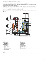
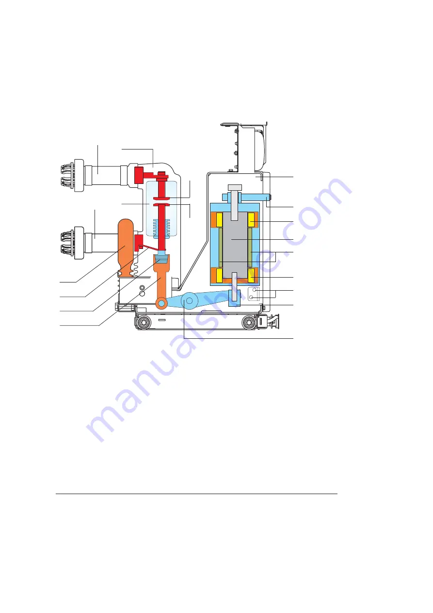
6.2. Structure of the circuit-breaker poles
The poles are installed in the rear part of the circuit-breaker frame (fig. 7).
The active parts of the poles (vacuum interrupters) are embedded in epoxy resin and protected
against shocks and other external agents.
With the circuit-breaker closed, the current flows from the top terminal (1) to the fixed contact (1a)
in the vacuum interrupter (4), and then through the moving contact (2a) and the flexible connector
(6) as far as the bottom terminal of the circuit-breaker (2).
The movement of the moving contact are ensured by the insulating tie-rod (8) and by the kinemat-
ics (9).
Fig. 7
1
Top terminal
1a
Fixed contact
2
Bottom terminal
2a
Moving contact
3
Pole in resin
4
Vacuum interrupter
5
Current sensor
6
Flexible connector
7
Contact pressure spring
8
Insulating tie-rod
9
Drive shaft
10
Run regulator
11
Position sensors
12
Closing coil
13
Permanent magnets
14
Moving armature
15
Opening coil
16
Device for manual emergency opening
17
Supporting structure
Summary of Contents for eVM1
Page 1: ...eVM1 Installation and service instructions 12 17 5 kV 630 1250 A 16 31 5 kA ...
Page 2: ...1 ...
Page 76: ...74 Fig 66 Fig 67 ...
Page 77: ...75 Fig 68 Fig 69 ...
Page 110: ...108 Notes ...
Page 111: ...1 ...


