19
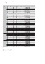
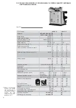
8.2.1. Withdrawable circuit-breakers for UniGear type ZS1 switchgear and PowerCube modules
Complete the circuit-breaker selected with the accessories indicated in para. 8.4.
Ur
Ir (40°C)
Isc
Dimensions
Type of
[kV]
[A]
[kA]
L [mm]
I [mm]
A [mm]
ø [mm]
circuit-breaker
12
630
16
650
150
205
35
eVM1/P 12.06.16 p150
630
20
450
150
205
35
eVM1/P 12.06.20 p150
630
25
450
150
205
35
eVM1/P 12.06.25 p150
630
31,5
450
150
205
35
eVM1/P 12.06.32 p150
1250
16
450
150
205
35
eVM1/P 12.12.16 p150
1250
20
450
150
205
35
eVM1/P 12.12.20 p150
1250
25
450
150
205
35
eVM1/P 12.12.25 p150
1250
31,5
450
150
205
35
eVM1/P 12.12.32 p150
17,5
630
16
450
150
205
35
eVM1/P 17.06.16 p150
630
20
450
150
205
35
eVM1/P 17.06.20 p150
630
25
450
150
205
35
eVM1/P 17.06.25 p150
630
31,5
450
150
205
35
eVM1/P 17.06.32 p150
1250
16
450
150
205
35
eVM1/P 17.12.16 p150
1250
20
450
150
205
35
eVM1/P 17.12.20 p150
1250
25
450
150
205
35
eVM1/P 17.12.25 p150
1250
31,5
450
150
205
35
eVM1/P 17.12.32 p150
Notes
L = Width of circuit-breaker.
I
= Horizontal poles center lines.
A = Upper and lower distance.
ø = Diameter of the isolating contact.
8.3. Control circuit power supply
The energy for circuit-breaker operation is supplied by one or more capacitors which are kept
charged by a feeder which also sees to supplying the electronic circuit with power.
This guarantees correct operation even if the auxiliary power supply does not reach the rated
value.
Thanks to the use of low consumption components, the feeder consumption is about 15 watt with
the circuit-breaker either closed or open.
After each operation, the feeder consumes about 110 watt for a few seconds to restore the opti-
mal charging level of the capacitors.
The charging condition of the capacitors is monitored constantly by the electronic module which
also sees to the opening, closing, signalling, etc. functions.
Two feeders are available:
type 1:
24...48 V a.c. / 24...60 V d.c.
type 2:
100...240 V a.c. / 110...250 V d.c.
Summary of Contents for eVM1
Page 1: ...eVM1 Installation and service instructions 12 17 5 kV 630 1250 A 16 31 5 kA ...
Page 2: ...1 ...
Page 76: ...74 Fig 66 Fig 67 ...
Page 77: ...75 Fig 68 Fig 69 ...
Page 110: ...108 Notes ...
Page 111: ...1 ...

