background image

E ZCLE A N

  |  CO M P R E SSED A I R SU P P LY U N I T  |  O I/E ZC L E A N - EN R E V. A

13

6  Maintenance

Annual maintenance

Ensure compressed air supply unit mountings are secure. 

Ensure push-fit couplings and 6 mm tubing are in serviceable 
condition – see "Pneumatic connections" on page 9 . 

Ensure the air intake is clean – see "System overview" on 
page 5, i
tem 

K

Ensure the air muffler/filter is clean and free of clogged 
pores – see "System overview" on page 5, item 

C

.  

To clean this, remove from the compressor head and blow 
oil-free compressed air through it from the reverse side. 
If the unit operates in a dusty environment, additional 
periodic cleaning may be required. Use only a clean, dry cloth. 

Summary of Contents for EZClean

Page 1: ... transmitter to enable automatic scheduled cleaning of the probe For more information Publications for the associated AWT420 transmitter and ADS420 optical dissolved oxygen probe are available for free download from www abb com measurement or by scanning these codes AWT420 transmitter ADS420 probe Search for or click on Commissioning Instruction AWT420 Universal 4 wire dual input transmitter CI AW...

Page 2: ...unting 7 Pole mounting 8 4 Connections 9 Pneumatic connections 9 Connect the tubing to compressed air unit 9 Connect the tubing to the ABB compressed air adaptor 9 Relay connections 10 Mains voltage supply 10 5 Configuration 11 Sensor Setup 12 6 Maintenance 13 Annual maintenance 13 7 Specifications 14 8 Spares and accessories 15 Spares 15 EZClean compressor maintenance kit 15 Air cleaning tubing k...

Page 3: ...ed air supply The EZClean system generates compressed air up to a pressure of 3 5 bar g 50 7 psi g maximum do not use compressed air for any other purpose than that for which it is provided never direct a stream of compressed air towards your body or the body of any other person when handling connecting compressed air lines the correct safety procedures must be observed suitable PPE must be worn g...

Page 4: ...those involved in the life cycle of electrical and electronic equipment In conformity with European local and national regulations electrical equipment marked with the above symbol may not be disposed of in European public disposal systems after 12 August 2005 NOTICE For return for recycling please contact the equipment manufacturer or supplier for instructions on how to return end of life equipme...

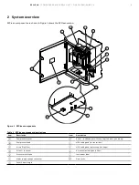
Page 5: ...lean component descriptions Item Description Item Description A Compressor motor H Air out bulkhead push fit coupling to 6 mm nylon tubing B Compressor head I M20 cable gland to transmitter C Air muffler filter J M20 cable gland mains supply voltage D Air out to sensor K Air intake including dust filter E Pressure relief valve L Instrument label F Mains supply voltage connector M Door locks G Fuse...

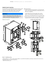
Page 6: ... sufficient space in front of the unit to open the door fully 280 mm 11 0 in Dimensions in mm in 330 13 0 395 15 5 205 8 1 381 15 0 262 10 3 420 16 5 440 17 3 196 7 7 Add 280 11 0 when door open Figure 2 Wall mounting Referring to Figure 2 1 Fit the four mounting lugs A to the compressor unit B in the required plane and secure using the M6 screws washers C 2 Mark appropriate mounting lug screw hol...

Page 7: ...2 1 6 U bolt 210 8 3 21 0 8 420 16 5 385 10 1 262 10 3 170 6 70 195 7 67 486 19 1 70 2 75 Figure 3 Handrail mounting Referring to Figure 3 1 Fit the four handrail mounting plates A to the compressor unit B in the required plane and secure each plate with one M6 screw C supplied If optional extension mounting plates D are required attach to the handrail mounting plate s in the required plane using ...

Page 8: ...1 330 13 0 50 1 9 U bolt 205 8 1 25 1 0 42 1 6 U bolt 205 8 1 21 0 8 420 16 5 Add 280 11 0 when door open Figure 4 Pole mounting Referring to Figure 4 1 Fit the pole mounting plate A to the compressor unit B and secure using the M6 screws C supplied 2 Position the compressor unit B on the pole and secure using the U bolt D and M8 nuts washers E supplied NOTICE It is not usually necessary to fit a ...

Page 9: ...onnect one end of the 6 mm OD nylon tubing A to bulkhead push fit connector B Figure 5 Connecting 6 mm OD nylon tubing to the compressed air unit 2 Proceed to Connect the tubing to the ABB compressed air adaptor to connect 6 mm OD nylon tubing to ABB compressed air adaptor Connect the tubing to the ABB compressed air adaptor Referring to Figure 6 1 Refer to the sensor accessories instructions for ...

Page 10: ...L1 connection on compressed air unit Figure 7 Relay connections compressed air unit to AWT420 transmitter 4 Tighten the cable glands on the compressed air unit and transmitter 5 Proceed to Mains voltage supply to make the mains voltage supply connection to the compressed air unit Mains voltage supply 230 or 115 V AC WARNING Isolate the compressed air unit and AWT420 transmitter from the mains powe...

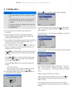
Page 11: ...sociated probe as follows Set Type to Output Set Source to Sx Clean where x corresponds to the sensor position 1 to 2 at the EZLink connector 5 Exit the Input Output menu and use the keys to scroll to the Sensor Setup menu Menu Sensor Setup Exit Select Press the key the Sensor Setup page is displayed 1 2 3 Sensor Setup S1 DO Salinity Units Pressure Units Back Select If more than 1 sensor is connec...

Page 12: ...ecs 30 Secs Clean Off Time Set the duration between cleans 1 to 60 Secs 30 Secs Number of Pulses Set the number of cleaning pulses 1 to 10 Pulses 2 Pulses Recovery Time Set the time delay between the completion of cleaning and the display of a new reading on the operator page 1 to 10 Min 1 Min Clean Duration Displays the total duration of the clean Clean Type set to Continuous Clean on Time Recove...

Page 13: ...umatic connections on page 9 3 Ensure the air intake is clean see System overview on page 5 item K 4 Ensure the air muffler filter is clean and free of clogged pores see System overview on page 5 item C To clean this remove from the compressor head and blow oil free compressed air through it from the reverse side If the unit operates in a dusty environment additional periodic cleaning may be requi...

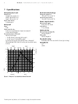
Page 14: ...n 2 0 bar g 30 psi g Typical operating pressure and flow rate 1 38 bar g 20 psi g 14 16 L min 0 5 scfm set to perform every 4 hours TORR BAR 0 200 400 600 760 0 5 1 0 1 5 2 0 25 20 15 10 5 30 0 10 20 30 10 20 0 1 0 3 0 4 0 5 0 6 0 7 0 8 0 9 0 2 INS HG PSIG LITRES M SCFM Figure 9 Pump unit pneumatic pressure flow rate Environmental ratings Storage temperature 20 to 50 C 4 to 122 F Operating tempera...

Page 15: ...pressor pneumatic fittings kit Part number Description 3KXA494400L0042 Compressor pneumatic fittings kit Accessories EZClean compressor pole mounting kit Part number Description 3KXA494400L0017 Compressor pole mounting kit includes compressor pole mounting plate U bolts nuts and washers EZClean compressor handrail mounting kit Part number Description 3KXA494400L0018 Compressor handrail mounting ki...

Page 16: ...ossible lack of information in this document We reserve all rights in this document and in the subject matter and illustrations contained therein Any reproduction disclosure to third parties or utilization of its contents in whole or in parts is forbidden without prior written consent of ABB Copyright ABB 2022 All rights reserved 3KXA494406R4201 ABB Measurement Analytics For your local ABB contact...

Reviews: