10
FAM3200
ARMORED VARIABLE AREA PURGEMETER | CI/FAM3200-EN REV. D
… 6 Electrical connections
… Analog indicator with alarm signaling
unit
Switching amplifier
Additional switching amplifiers are needed to operate the alarm
signaling units.
See
Switching amplifier
on page 10 and the ‘Ordering
Information’ section of the data sheet for further information.
Specifications
Power supply
230 V AC, +10 % /
−15
%, 45 to 60 Hz
115 V AC, +10 % /
−15
%, 45 to 60 Hz
24 V DC, +10 % /
−15
%
Output
One or two switching relays with potential-free
changeover contacts
Switching capacity
Maximum 250 V, maximum 4 A, maximum 500 VA
Maximum permissible
cable length
Between the switching amplifier and alarm
signalling unit:
300 m (984 ft)
Permissible ambient
temperature range
−
20 to 60 °C
(−4
to 140 °F)
Electrical connection
Screw terminals, maximum 2.5 mm
2
(14 AWG)
Type of assembly
35 mm top-hat rail in accordance with
EN 60715:2001
IP rating
IP 20 in accordance with EN 60529
Weight
approx. 150 g (0.3 lb)
Analog indicator with transmitter
Specifications
Output signal
4 to 20 mA, two-wire technology
Power supply
maximum 30 V DC
Input Current
maximum 30 mA
Connection type
Cable, 2-
wire, brown (+) / blue (−), length
1.75 m (5.74 ft)*
Ambient temperature range
−
20 to 40
°C (−4
to 104 °F)
Design
Angular position transmitter in two-wire
technology
* Other cable lengths available on request.
7
Commissioning
CAUTION
Risk of burns due to hot measuring media
The device surface temperature may exceed 70 °C (158 °F),
depending on the measuring medium temperature!
• Before starting work on the device, make sure that it has
cooled sufficiently.
During commissioning of the flowmeter, observe the following
points:
• The ambient and operating conditions (pressure,
temperature, power supply) must correspond to the
details on the name plate and the specifications.
• Open the shut-off valves slowly to prevent pressure
surges that can damage the flowmeter.
• For liquid measurement media, vent the piping if
necessary.
• For devices with alarm signalling units, set the units to
the required switching points.
Adjusting the alarm signalling unit
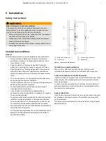
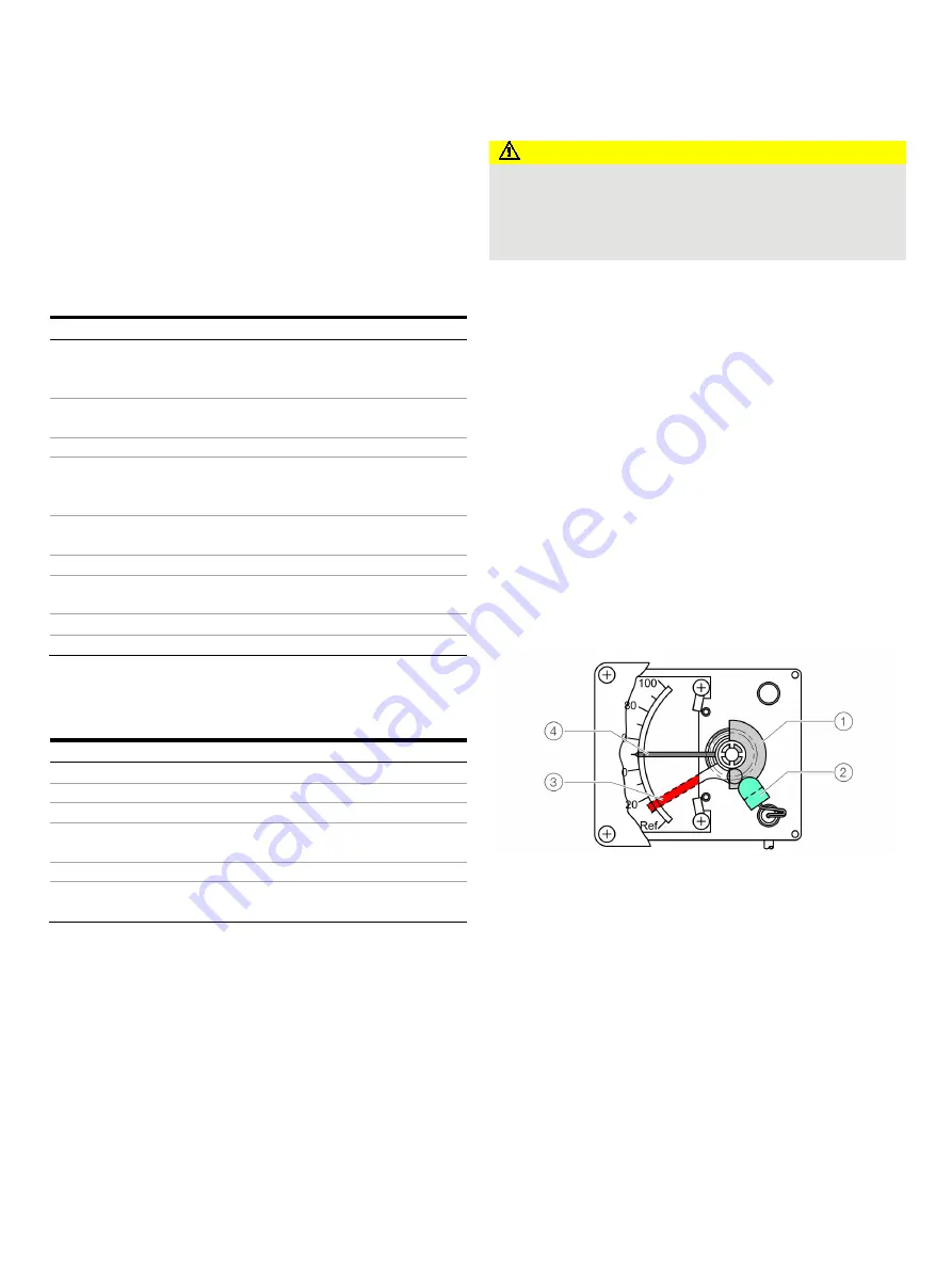
The alarm signalling unit is designed as a proximity switch. When
inserted in the proximity switch, the metal tag initiates the
switching process. The switching point can be adjusted with a
screwdriver.
1
Metal tag
2
Alarm signalling unit (proximity
switch)
3
Alarm setting
4
Pointer
Figure 5: Single alarm (example)
1.
Unscrew the housing cover.
2.
Adjust the alarm setting to the required switching point
using a flat-bladed screwdriver.
3.
Screw on housing cover.
Operating instructions
If there is a chance that safe operation is no longer possible,
take the device out of operation and secure it against
unintended startup.

