background image


FAM3200

 | CI/FAM3200-EN Rev. B  11


6.2.5


Heat tracing 

Trace heating may be used under the following conditions: 
—  The heat tracing must be installed in a way that ensures 

there is no temperature increase in the indicator housing. 

—  The maximum permitted temperature of the heat tracing 

must not exceed the permitted measuring medium 
temperature. 

—  When using electrical heat tracing, attention must be paid 

to potential functional impairment by electromagnetic 
fields. 


6.3


Operating conditions 

A variable area flowmeter is specified for a defined set of 
operating conditions of the measuring medium. For liquids and 
gases, these are pressure and temperature-related properties 
(density and viscosity) under operating conditions. 
For gases, in particular, this means operating at a specific 
operating pressure and operating temperature. The specified 
accuracy of the device always refers to the operating 
conditions underlying the specification. 
 

6.3.1


Pressure loss 

The available operating pressure at the measuring point must 
be higher than the pressure loss listed for the flowmeter in the 
specifications. 
It is important to also consider the pressure loss downstream 
from the flowmeter due to losses in the piping and other 
fittings. 
 
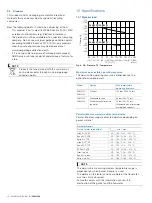
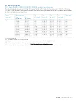
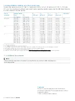
For information on pressure loss, see chapter "Measuring 
range table" on page 17. 


6.3.2


Prevention of compression oscillations when 
measuring gases 

With low flow amounts and low operating pressure, so-called 
compression oscillations of the float can occur. 
If the maximum upstream pressure listed in the specifications 
is not reached, the flowmeter can optionally be equipped with 
a mechanical float damper.  
Damping is available for the device types FAM3225 and 
FAM3255 with a process connection size > 1/4". 
 
To prevent self-generated compression oscillations, note the 
following information from VDI / VDE 3513 Sheet 3: 
—  Select a flowmeter with the lowest possible pressure loss. 
—  Minimize the piping length between the flowmeter and the 

closest up or downstream throttling location. 

—  Restrict the usual measuring range from the usual 

10 … 100 % to 25 … 100 %. 

—  When setting the flow rate value, always start assuming 

larger values. 

—  Increase the operating pressure and consider its effect on 

the flow rate values due to the change in gas density at 
the new operating conditions. 

— Minimize 

non-throttled, 

free volumes upstream and 

downstream of the device. 


6.3.3


Pressure shocks 

Especially when measuring gases, it is possible that pressure 
or shock waves can occur when fast opening solenoid valves 
are employed and the piping cross-sections are not throttled, 
or if there are gas bubbles in liquids. 
As a result of the sudden expansion of the gas in the piping, 
the float is forcibly driven against the upper floatstop. 
Under certain conditions, this can lead to destruction of the 
device. 
The mechanical float damping is not suitable for the 
compensation of pressure shocks! 
 

Summary of Contents for FAM3200 Series

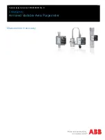
Page 1: ...Commissioning Instruction CI FAM3200 EN Rev B FAM3200 Armored Variable Area Purgemeter Measurement made easy ...

Page 2: ...entation on FAM3200 is available to download free of charge at www abb com flow Alternatively simply scan this code Manufacturer ABB Automation Products GmbH Measurement Analytics Dransfelder Str 2 37079 Göttingen Germany Tel 49 551 905 0 Fax 49 551 905 777 Customer service center Tel 49 180 5 222 580 Mail automation service de abb com Change from one to two columns ...

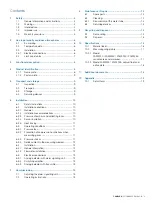
Page 3: ...g conditions 11 6 3 1 Pressure loss 11 6 3 2 Prevention of compression oscillations when measuring gases 11 6 3 3 Pressure shocks 11 6 3 4 Solids content in the measuring medium 12 6 4 Installation 12 6 4 1 General information 12 6 4 2 Flowmeter installation 12 6 5 Electrical connections 12 6 5 1 Analog indicator with alarm signaling unit 12 6 5 2 Switching amplifier 13 6 5 3 Analog indicator with...

Page 4: ...unstable liquids and gases and vapors To measure the flow of the operating volume under constant operating conditions pressure temperature density An output of the flow is also possible in standard or mass units The device has been designed for use exclusively within the technical limit values indicated on the name plate and in the data sheets The following technical limit values must be observed ...

Page 5: ...t for external loads e g as a support for piping etc Material application e g by painting over the name plate or welding soldering on parts Material removal e g by spot drilling the housing 1 5 Warranty provisions Using the device in a manner that does not fall within the scope of its intended use disregarding this manual using underqualified personnel or making unauthorized alterations releases t...

Page 6: ... 2 3 Installation Observe the following points when installing the devices in potentially explosive atmospheres The alarm signalling units must only be connected to certified intrinsically safe circuits When using electrical heat tracing attention must be paid to potential functional impairment by electromagnetic fields The specifications of EN 60079 14 must be observed Use with zone 0 in the mete...

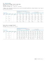
Page 7: ...40 60 140 60 140 60 140 60 140 60 140 60 140 52 169 50 122 60 140 60 140 35 95 60 140 60 140 25 77 60 140 60 140 76 242 10 50 50 122 60 140 35 95 60 140 25 877 50 122 Devices for use in category 2 zone 1 Equipment Tmedium Tambient 20 C 4 F Permissible ambient temperature Tambient 40 C 104 F 50 C 122 F 60 C 140 F Electrical data Permissible measuring medium temperature Tmedium in the relevant tempe...

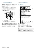
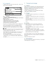
Page 8: ...fferential pressure regulators The devices are also available with an angular position transmitter with 4 20 mA output signal as an option 4 Product identification 4 1 1 Name plate The name plate is located on the indicator housing Fig 3 Name plate example 1 Type designation 2 Serial number 3 Order number 4 ATEX marking 5 Ambient temperature 6 Measuring medium temperature 7 Maximum flow rate 8 Det...

Page 9: ... improper transport Details of any damage that has occurred in transit must be recorded on the transport documents All claims for damages must be submitted to the shipper without delay and before installation 5 2 Transport The center of gravity of some devices is not at the center of the equipment Use the any available attachment points on the device for transport Ensure that all transport locking...

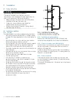
Page 10: ... valves If the flowmeter is installed in a pipeline where decommissioning is impossible or inexpedient a bypass line should be provided For gaseous measurement media the flowmeter should be installed as close as possible to the pipe constrictions The nominal diameter of the piping at the outlet of the flowmeter should be measured as small as possible Shut off and throttle valves should preferably ...

Page 11: ...oscillations when measuring gases With low flow amounts and low operating pressure so called compression oscillations of the float can occur If the maximum upstream pressure listed in the specifications is not reached the flowmeter can optionally be equipped with a mechanical float damper Damping is available for the device types FAM3225 and FAM3255 with a process connection size 1 4 To prevent se...

Page 12: ...d position using the correct threaded connections When tightening the process connections on the flowmeter use a spanner of the corresponding size to counter the force Model Meter size Wrench size mm FAM3220 FAM3250 1 4 SW 22 FAM3225 FAM3255 1 4 SW 19 3 8 SW 24 1 2 SW 27 1 SW 50 Check the process connections for tightness 6 5 Electrical connections 6 5 1 Analog indicator with alarm signaling unit ...

Page 13: ...vailable on request 7 Commissioning CAUTION Risk of burns due to hot measuring media The device surface temperature may exceed 70 C 158 F depending on the measuring medium temperature Before starting work on the device make sure that it has cooled sufficiently During commissioning of the flowmeter observe the following points The ambient and operating conditions pressure temperature power supply m...

Page 14: ...rized customer service personnel When replacing or repairing individual components use original spare parts NOTE Spare parts can be ordered from ABB Service Please contact Customer Center Service acc to page 2 for nearest service location 8 2 Cleaning Soiling of the meter tube and the float will impair the measuring accuracy of the device The necessary cleaning interval is dependent on the operati...

Page 15: ... shipping purposes All devices delivered to ABB must be free from any hazardous materials acids alkalis solvents etc Please contact Customer Center Service acc to page 2 for nearest service location 9 Recycling and disposal 9 1 Dismounting WARNING Risk of injury due to process conditions The process conditions e g high pressures and temperatures toxic and aggressive measuring media can give rise t...

Page 16: ...evice equipment Model Option Max permissible operating pressure FAM3225 FAM3255 Without 100 bar 1450 38 psi FAM3220 FAM3250 With needle valve 40 bar 580 15 psi With differential pressure regulator 14 bar 203 05 psi Standard higher pressures available on request Permissible measuring medium temperature Permissible measuring medium temperature depending on gasket material Gasket materials O ring met...

Page 17: ...4H 6 1 59 230 8 12 18 18 0 7 10 15 1 0 14 5 8 0 12 05H 10 2 64 350 12 36 18 18 0 7 10 15 1 0 14 5 8 0 12 06H 16 4 23 540 19 07 18 18 0 7 10 15 1 0 14 5 8 0 12 07H 25 6 6 850 30 02 18 18 0 7 10 15 1 0 14 5 9 0 13 08H 40 10 57 1250 44 14 18 18 0 7 10 15 1 0 14 5 10 5 0 15 09H 60 15 85 1900 67 1 18 18 0 7 10 15 1 0 14 5 12 5 0 18 10H 100 26 42 3100 109 48 12 12 7 1 0 14 5 17 0 0 25 11H 1 Connection n...

Page 18: ... 130 1 89 34H 1 800 211 34 23800 840 49 3 3 16 232 06 0 4 5 8 60 0 87 40H 1000 264 17 29700 1048 85 3 3 16 232 06 0 4 5 8 62 0 9 41H 1600 422 68 47600 1680 98 3 3 16 232 06 0 4 5 8 74 1 07 42H 2000 528 34 59500 2101 22 3 3 16 232 06 0 4 5 8 85 1 23 43H 2500 660 43 74400 2627 41 3 3 16 232 06 0 4 5 8 105 1 52 44H 3000 792 52 89300 3153 6 3 3 16 232 06 0 4 5 8 130 1 89 45H 1 Connection nominal size ...

Page 19: ...ess Contact person Telephone Fax E Mail Device details Typ Serial no Reason for the return description of the defect Was this device used in conjunction with substances which pose a threat or risk to health Yes No If yes which type of contamination please place an X next to the applicable items Biological Corrosive irritating Combustible highly extremely combustible Toxic Explosiv Other toxic subs...

Page 20: ...kte de abb com www abb com flow Note We reserve the right to make technical changes or modify the contents of this document without prior notice With regard to purchase orders the agreed particulars shall prevail ABB does not accept any responsibility whatsoever for potential errors or possible lack of information in this document We reserve all rights in this document and in the subject matter an...

Reviews: