background image

14 

ABB i-bus

®

 EIB / KNX

System setup

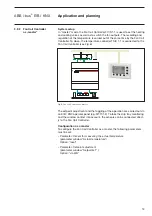
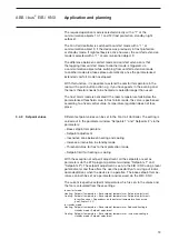
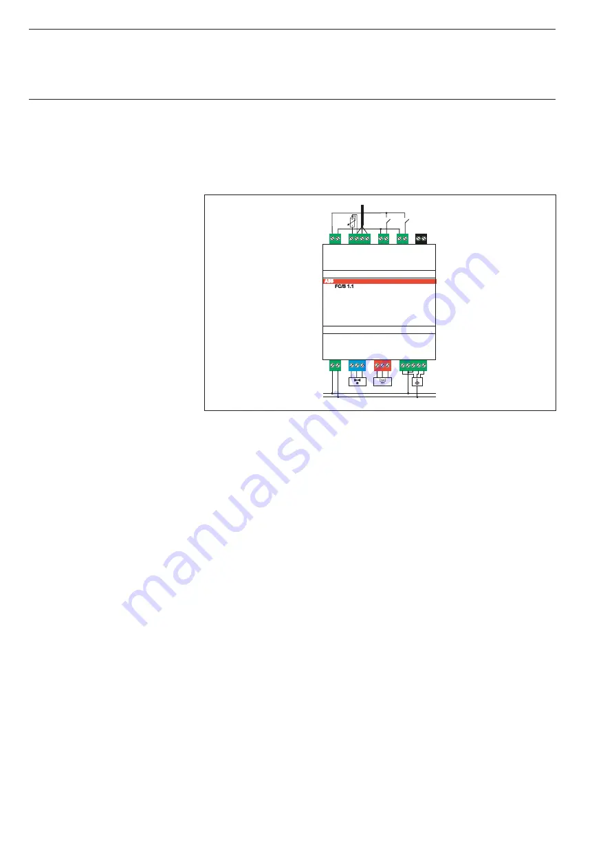
In “stand-alone” mode, the Fan Coil Controller FC/S 1.1 takes over the 
recording of the actual temperature, complete control, the setting of the 
heating and cooling valves as well as the switching of the fan outputs. 
To do so, the temperature sensor TS/K 1.1 must be connected to the 
Fan Coil Controller (see Fig. 7).


Fig. 7: Fan Coil Controller as “stand-alone”

The setpoint adjustment is carried out via a potentiometer which can be 
connected directly to the Fan Coil Controller. To take the drip tray monitoring 
and the window contact into account, the sensors can be connected 
directly to the Fan Coil Controller.

Configuration as a stand-alone device

To configure the Fan Coil Controller as a stand-alone device, the following 
parameters must be set:

–  Parameter: 

Sensor for measuring the actual temperature


(parameter window “Actual temperature”)
Option: “local”

–  Parameter: 

Setpoint adjustment

(parameter window “Setpoints 1”)
Option: “local”

Application and planning

3.2.3  

Fan Coil Controller
as „stand-alone“

1

3

L
N

Summary of Contents for FC/S 1.1

Page 1: ...Product manual ABB i bus EIB KNX Fan Coil Controller FC S 1 1 Intelligent Installation Systems ...

Page 2: ...des and setpoint adjustment 18 3 4 1 Operation modes 18 3 4 2 Setpoint values 19 3 4 3 Setpoint correction dependent on external temperature 20 3 5 Valve drives valves and controllers 21 3 5 1 Valve drives 21 3 5 2 Valve characteristics 23 3 5 3 Types of control 24 4 Project design and programming 4 1 Description of the communication objects 27 4 2 Description of the parameters 34 4 2 1 Parameter ...

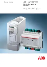
Page 3: ...valves Multi speed fans with up to three fan speeds can be switched via floating contacts Two binary inputs are also available for monitoring windows and the formation of condensed water The Fan Coil Controller can either be integrated in the building installation system via the EIB or operated independently as an autonomous temperature controller To do so the temperature sensor TS K 1 1 must be c...

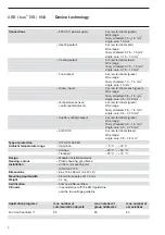
Page 4: ...oling outputs 2 semi conductor switches For connecting motor driven raise lower valve drives or thermal 24 V AC valve drives max 5 W Nominal voltage 24 V AC Nominal current 250 mA Continuous load max 5 W resistive Cable length max 20 m Fan outputs 3 floating contacts for connecting fans with up to 3 speeds Nominal voltage 230 V AC Nominal current 6 A Auxiliary voltage outputs For supplying the bin...

Page 5: ...ded 0 5 1 5 mm 2 single core 0 5 0 75 mm 2 Auxiliary voltage output 2 screw terminals green Wire range finely stranded 0 5 1 5 mm2 single core 0 5 0 75 mm2 EIB KNX 3 screw terminals black Wire range single core 0 3 0 5 mm2 Type of protection IP 20 EN 60 529 Ambient temperature range Operation 5 C 45 C Storage 25 C 55 C Transport 25 C 70 C Design Modular installation device Housing colour Plastic h...

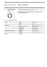
Page 6: ...Device technology 2 3 Product and functional description TS K 1 1 2 4 Technical data for TS K 1 1 Cable Cables 3 core cable Length 2 m Colour grey Connections Type Plug in screw terminal strip Module slot on FC S 1 1 Temp sensor Green cable Screw terminal 1 White cable Screw terminal 2 Brown cable Screw terminal 3 Ambient temperature range Operation 25 C 60 C Storage 25 C 60 C Transport 25 C 70 C ...

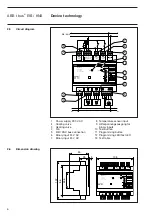
Page 7: ... J5 EIB Error J2 J3 J4 1 0 1 0 Function LED Test Mode Un 230 V In 40 mA F 50 60 Hz 1 2 3 4 5 L L J4 1 2 3 J3 1 2 3 J2 Input 230 V AC J1 1 2 Input 24 V AC J9 2 1 4 3 2 1 Temp Sensor FC Temp 02 J8 Input 24 V AC J7 2 1 Input 24 V AC J6 2 1 2 1 J5 EIB KNX 1 2 3 L N L N 4 13 12 3 11 10 5 6 7 1 2 9 8 105 FC S 1 1 ABB i bus Test Progr J5 EIB Error J2 J3 J4 1 0 1 0 Function LED Test Mode Un 230 V In 40 mA...

Page 8: ...e with the parameter settings Test function When the 230 V AC power supply is applied a test function of the device outputs can be activated to check the connected valves and fans The test can also be conducted without a downloaded application program and without an EIB KNX connection The programming LED continually indicates the current status of the EIB KNX bus voltage By pressing the test butto...

Page 9: ... test levels 6 and 7 The cooling valve is opened flashes 6 times or closed flashes 7 times with the next two push button actions If there is a short circuit at one of the valve outputs the test func tion is immediately interrupted within the corresponding test level Device technology ...

Page 10: ...s The heat exchangers and the fan are the most important components of a fan coil unit see Fig 2 The hot or cold water flows into the heat exchangers depending on the room temperature required The flow of water through the heat exchangers is controlled via the valves Fig 2 Structure of a fan coil unit Application and planning 3 Application and planning 3 1 Heating ventilation and air conditioning ...

Page 11: ...oling which are each triggered via a valve see Fig 3 Fig 3 Pipe systems The 3 pipe version functions in a similar way to the 4 pipe version It also has a separate inlet for hot and cold water as well as two separate heat exchangers each with a valve In contrast to the 4 pipe version the 3 pipe version has a common return flow for hot and cold water The 2 pipe version consists of a single water cir...

Page 12: ...able as upright units for wall and ceiling mounting Built in devices are supplied without housing and are mounted in the wall ceiling or in the floor The air is blown through a screen into the room Air intake Fan coil units are available as devices with circulating air or mixed air In devices with circulating air the ambient air is fed from the fan past the heat exchangers In mixed air devices the...

Page 13: ...NX room thermostat To take the drip tray monitoring and the window contact into account the sensors can be connected directly to the Fan Coil Controller For the correct execution of the function the room thermostat must send both the actual temperature and the respective operation mode see Chapter 3 4 1 via the EIB KNX to the Fan Coil Controller Configuration as a slave To configure the Fan Coil C...

Page 14: ...l Controller as master The setpoint adjustment and the toggling of the operation are carried out via an EIB KNX operator panel e g MT701 2 To take the drip tray monitoring and the window contact into account the sensors can be connected direct ly to the Fan Coil Controller Configuration as a master To configure the Fan Coil Controller as a master the following parameters must be set Parameter Sens...

Page 15: ... carried out via a potentiometer which can be connected directly to the Fan Coil Controller To take the drip tray monitoring and the window contact into account the sensors can be connected directly to the Fan Coil Controller Configuration as a stand alone device To configure the Fan Coil Controller as a stand alone device the following parameters must be set Parameter Sensor for measuring the act...

Page 16: ...t fan control a fan drive is connected directly to the Fan Coil Controller and switched via three floating contacts It is possible to connect a 1 speed 2 speed or 3 speed fan The Fan Coil Controller sets the fan speed depending on a value that is received via the EIB KNX The value is received as a 1 byte value at the communication object Fan Manual operation of fan The conversion of the 1 byte val...

Page 17: ...he telegram value received Configuration on off A 1 speed fan can be controlled via the 1 bit communication object Fan Fan on off The following parameters must be set during the configuration Parameter Type of fan parameter window Fan Option EIB on off Configuration 3 speeds A 3 speed fan can be controlled via the three 1 bit communication objects Fan Speed X The following parameters must be set d...

Page 18: ...ter Type of fan parameter window Fan Option local Parameter Number of fan speeds parameter window Fan Option 1 The communication objects Switch output Switch output 2 and Switch output Switch output 3 are linked with the corresponding group address for lighting control If one of these communication objects receives a 1 the corresponding output is switched on If a 0 is received the output is switch...

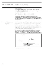
Page 19: ...ived the output is switched off The Fan Coil Controller can be operated in the following modes comfort mode comfort extension standby mode night setback frost protection heat protection frost alarm The toggling between the operation modes is carried out via communication objects The correlation is represented in Fig 10 Fig 10 Mode selection via communication objects 3 4 Operation modes and setpoin...

Page 20: ... values can be set in the Fan Coil Controller The setting is carried out in the parameter window Setpoints 1 and Setpoints 2 via the parameters Base setpoint temperature Setpoint adjustment Insensitive zone between heating and cooling Increase or reduction in standby mode Threshold value for frost or heat protection mode Setpoint limit for heating or cooling With the exception of setpoint adjustme...

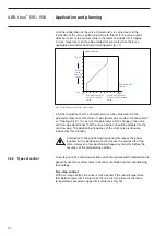
Page 21: ... tempe rature is provided for comfort mode This function automatically adapts the setpoint temperature to the external temperature when cooling the room and thus represents an additional restriction of the setpoint temperature The correction of the setpoint is set from the parameterised threshold value of the external temperature parameter Minimum external temperature for correcting the setpoint p...

Page 22: ...th the Fan Coil Controller The Fan Coil Controller supports the control of electromotive raise lower valve drives These valve drives are connected to the Fan Coil Controller via three connecting cables neutral conductor switched phase for open switched phase for closed see Fig 12 With raise lower valve drives the valve can be opened to any percentage value and this position is retained for a longe...

Page 23: ... connected to the Fan Coil Controller via two connecting cables switched phase and neutral conductor for AC valve drives or and for DC valve drives see Fig 13 Fig 13 Connection of electrothermal valve drives EIB valve drives If EIB valve drives are used e g ST K 1 1 the outputs of the Fan Coil Cont roller remain free The Fan Coil Controller sends the calculated control value via the EIB The EIB va...

Page 24: ...ted for different valve types Many valves have for example almost no flow when they are slightly opened and already reach their maximum flow rate at 60 80 There is also the fact that a disruptive whistling noise is generated in many valves with a low flow rate These effects can be taken into account by limiting the active valve opening range see Fig 16 The positioning frequency of the valve drive ...

Page 25: ... The positioning frequency of the valve drive is likewise reduced by this function A reduction in the positioning frequency decreases the power required for the positioning and increases the service life of the valve However a low positioning frequency also diminishes the accuracy of the temperature control Two step control continuous action control and pulse width modulation are generally used to...

Page 26: ...p control is not supported by the Fan Coil Controller Continuous action control With continuous action control a control value is calculated from the actual temperature and the setpoint temperature and then used for the opti mum regulation of the temperature The valve is moved to a position which corresponds to the calculated control value The valve can thereby be fully opened fully closed and mov...

Page 27: ...culated control value in a similar way to continuous action control The control value is fixed for a cyclic period and converted into the valve opening duration For example the control value 20 is converted at a cyclic period of 15 minutes into a valve opening time of 3 minutes The control value 50 produces a valve opening time of 7 5 minutes see Fig 20 Fig 20 Pulse width modulation With pulse wid...

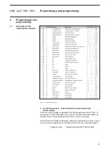
Page 28: ...r TS K 1 1 connected the actual temperature is sent to this communication object via the EIB KNX The parameterised Correction value is included If the Fan Coil Controller is operated without the temperature sensor it recei ves the actual temperature via the EIB KNX at this communication object Telegram value Coded value see EIB KNX manual 4 Project design and programming 4 1 Description of the com...

Page 29: ...Telegram value 0 No error 1 Error 4 Setpoint Base setpoint temperature EIS 5 2 Byte The Fan Coil Controller receives the base setpoint temperature at this communication object Telegram value Coded value see EIB KNX manual 5 Setpoint Setpoint adjustment EIS 5 2 Byte The Fan Coil Controller receives the setpoint adjustment at this communication object Telegram value Coded value see EIB KNX manual 6 ...

Page 30: ...etback EIS 1 1 Bit The Fan Coil Controller is switched to night setback mode via this communication object Telegram value 0 No function 1 Night setback 12 Mode selection ON command for frost protection EIS 1 1 Bit The Fan Coil Controller is switched to frost protection or heat protection via this communication object Telegram value 0 No function 1 Frost protection heat protection 13 Window contact...

Page 31: ...tion of fan The fan speeds are automatically controlled by the Fan Coil Controller in automatic mode Telegram value 0 No function 1 Automatic mode activated 17 Fan Fan status manual automatic EIS 1 1 Bit Using this communication object the status of the fan operation mode is reported back via the EIB KNX Telegram value 0 Manual 1 Automatic mode activated 18 Fan Speed 1 EIS 1 1 Bit 19 Fan Speed 2 E...

Page 32: ...tinuous action control Telegram value 0 Valve fully closed 0 Intermediate position 255 Valve fully open 100 21 Heating valve Output for heating valve EIS 1 1 Bit 22 Cooling valve Output for cooling valve EIS 1 1 Bit These communication objects are only visible if the option EIB valve pulse width modulation is selected for the parameter Type of heating valve or Type of cooling valve Using this comm...

Page 33: ...er than the parameterised Maximum value for the duration of the parameterised Alarm delay Telegram value 0 No error 1 Temperature error 27 Drip tray overflow Drip tray overflow signal EIS 1 1 Bit The Fan Coil Controller sends a drip tray overflow signal via this communi cation object This communication object is only visible if the option Drip tray monitoring normal or Drip tray monitoring inverte...

Page 34: ...ains no information A status byte table with all the possible combinations is printed in the appendix see Chapter 5 1 30 Status Status of fan coil controller 2 Byte non EIS The operating state of the Fan Coil Controller is sent via the EIB KNX using this communication object Cooling is automatically deactivated in the event of a drip tray overflow Telegram code 1st byte 76543210 Telegram value 0 D...

Page 35: ...switch outputs of the Fan Coil Controller If the option local max 3 speeds is set for the parameter Type of fan incoming telegrams at this communication object are not executed The floating outputs of the Fan Coil Controller are switched on or off via these communication objects for example to control the lighting or an electric heating system Telegram value 0 Output off contact open 1 Output on c...

Page 36: ...mmon valve e g 2 pipe system Minimum changeover time between heating and cooling Options min 2 255 60 Setting the minimum pause in minutes when toggling between heating mode and cooling mode Delay after manual override of fan Options min 0 255 10 Setting the period in minutes after which the fan is reset to automatic mode after the last telegram at the communication object Fan Manual operation of ...

Page 37: ... actual value received via the EIB KNX Monitoring period of actual temperature Options min 2 255 10 Setting the monitoring period for the actual temperature local and via the EIB KNX If a sensor value is received via the EIB KNX the monitoring period should be selected so that it is at least twice as long as the cyclical transmission period of the sensor so that an error message is not sent immedi...

Page 38: ...temperature This parameter is only visible if the option local is set for the parameter Sensor for measuring the actual temperature Period for cyclical sending Options min 2 255 2 Setting the cyclical transmission period for the actual temperature This parameter is only visible if the option on is selected for the parameter Cyclical sending Differential value for sending Options C 0 1 1 0 0 5 Sett...

Page 39: ... value i e to 30 C the setpoint is adapted to 26 C If the external temperature rises to over 33 C the setpoint is 27 C etc Correction of external temperature Options C 3 0 3 0 0 0 Correction of the external temperature received via the EIB KNX Monitoring period for external temperature Options min 2 255 10 Setting the monitoring period for the external temperature The monitoring time should be sel...

Page 40: ...s set locally via a potentiometer which is connected to the Fan Coil Controller the option locally must be set Insensitive zone between heating and cooling Options C 0 5 6 0 4 0 Setting the insensitive zone in degrees centigrade A small insensitive zone increases the control precision i e an optimum achievement of the setpoint temperature A large insensitive zone enables higher energy savings due ...

Page 41: ...parameter is only visible if the option on is set for the parameter Setpoint correction dependent on external temperatu re for cooling see parameter window External temperature The adaptation of the setpoint is always 1 C per 3 C change in the external temperature Example The setpoint is 25 C The parameterised threshold value is 27 C If the external temperature now increases by 3 C above the thres...

Page 42: ... during night setback The reduction or increase in the temperature is calculated starting with the base setpoint temperature Actual temperature threshold in frost protection mode Actual temperature threshold in heat protection mode Options for frost protection C 2 10 7 Options for heat protection C 5 40 35 Frost protection mode Setting the minimum frost protection temperature When this temperature...

Page 43: ...y select the option user defined for the parameters Controller setting for heating and Controller setting for cooling if you have sufficient knowledge in heating and cooling technology so that the appropriate settings are carried out correctly The options slow normal and fast are suitable for standard applications Fig 27 Parameter window Controller Controller setting for heating Controller setting...

Page 44: ...ending of the control value on the EIB KNX via the communication object Controller Control value for PI controller Period for cyclical sending of control value Options min 2 255 2 Setting the cyclic transmission time for the control value This parameter is only visible if the option on is set for the parameter Sending of control value Differential value for sending the control value Options 1 10 3...

Page 45: ...oggling of the fan speed de pendent on the control value of the controller This parameter is only visible if the option local max 3 speeds EIB 3 speeds or EIB 0 100 has been selected for the parameter Type of fan Starting characteristic of fan Options switch on at speed 1 switch on at speed 2 switch on at speed 3 Setting the speed at which the fan switches on To ensure that the fan motor starts re...

Page 46: ...ing the minimum delay at a fan speed This parameter should be selected so that a fault is avoided by changing over the fan speed too frequently This parameter is only visible if the option local max 3 speeds or EIB 3 speeds has been set for the parameter Type of fan Fig 30 Parameter window Valves Control value for closing point of valve Control value for fully opened valve Options 0 100 10 40 Adju...

Page 47: ...ction if the valve is controlled via the heating cooling out puts of the Fan Coil Controller Control direction of heating valve Control direction of cooling valve Options normal de energised closed inverted de energised open Setting the control direction of the valve Valve adjustment Options off on User defined adjustment of the valve characteristics If the option on is selected the parameters for...

Page 48: ...e valve position should be adapted to the control value The larger the parameterised value that is selected the less frequently the valve needs to be positioned This parameter is only visible if the option raise lower valve continuous has been set for the parameter Type of heating valve or Type of cooling valve Cycle time for heating valve Cycle time for cooling valve Options for heating valve min...

Page 49: ...nsor contact open window open contact closed window open Input normal Input inverted Setting a local window contact or a binary input The options contact open window open and contact closed window open are used for a window contact In the case of a window contact the Controller function for open window is executed when the contact is closed or opened The status is reported via the EIB communicatio...

Page 50: ...value remains unchanged until the window is closed again The control value is then recalculated and the valve position is adjusted If the option normal active is selected the current control value is continually calculated in spite of the open window and the valve position is adjusted If the option control value 0 all off is selected the valve is closed The frost protection function or heat protec...

Page 51: ... an EIB dew point detector Floating contacts are preferably used for drip tray monitoring Slow wave movements can be produced in the drip tray due to external vibrations which lead to a continuous opening and closing of the contact This effect can be counteracted using a debounce time of an appropriate length Sending of error signal Options no repetition cyclic repetition Activation of the cyclica...

Page 52: ...clic repetition is set the object value is sent according to the parameterised Period for cyclical sending of frost alarm Period for cyclical sending of frost alarm Options min 2 255 5 Setting of the cyclic transmission time for a frost alarm This parameter is only visible if the option cyclic repetition is set for the parameter Repetition of frost alarm Variable temperature limit value monitoring...

Page 53: ... cyclic transmission function for variable temperature monitoring If the option cyclic transmission is set the object value is sent according to the parameterised Period for cyclical sending of frost alarm Control value heating when actual temperature is absent or in event of frost Options 0 100 25 Setting the control value in frost protection mode This control value is set if the value falls belo...

Page 54: ...e Hexadecimal free free free free Temperature monitoring Frost alarm External temperature error Actual temperature error 0 00 1 01 2 02 3 03 4 04 5 05 6 06 7 07 8 08 9 09 10 0A 11 0B 12 0C 13 0D 14 0E 15 0F Bit no 7 6 5 4 3 2 1 0 Status byte value Hexadecimal free free free free Drip tray overflow Window open Cooling active Heating active 0 00 1 01 2 02 3 03 4 04 5 05 6 06 7 07 8 08 9 09 10 0A 11 ...

Page 55: ...ering information Short code bbn 40 11395 EAN Price group Unit weight kg Pack unit pc Order no Room thermostat solo FM TUS U 1 1 GJ B000 6134 A0157 04202 1 17 0 05 1 Room thermostat alpha nea FM TU W 1 1 GJ B000 6134 A0137 00162 2 17 0 1 1 Busch triton switch sensors with room thermostat FM TRITON 3 D RT WA 1 GJ B000 6300 A1224 98573 1 17 0 08 1 Busch triton switch sensors with room thermostat FM ...

Page 56: ...The information in this leaflet is subject to change without further notice Pub No 2CDC 508 032 D0201 Your EIB Partner ...

Reviews: