3
ABB i-bus
®
EIB / KNX
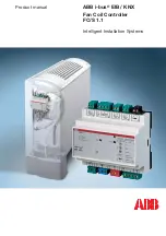
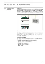
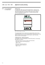
The Fan Coil Controller controls motor-driven and thermal heating and coo-
ling valves as well as multi-speed fans via the ABB i-bus EIB or as a stand-
alone device in combination with the temperature sensor TS/K 1.1.
There are two binary inputs available for 24 V AC signalling contacts for
window and drip tray monitoring. The 24 V AC auxiliary voltage for scanning
the binary inputs is made available by the device. The Fan Coil Controller
requires a 230 V AC power supply. All the connections are established via
screw/plug-in terminals.
Device technology
2 Device
technology
2.1
Product and functional
description FC/S 1.1
2.2
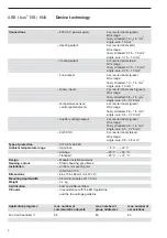
Technical data for FC/S 1.1
Power supply
– Operating voltage
230 V AC +/– 10 %, 50 … 60 Hz
– Power consumption via EIB
max. 250 mW
– Total power consumption
max. 9 W
Heating/cooling outputs
– 2 semi-conductor switches
For connecting motor-driven,
raise/lower valve drives or
thermal 24 V AC valve drives
(max. 5 W)
– Nominal voltage
24 V AC
– Nominal current
250 mA
– Continuous load
max. 5 W (resistive)
– Cable length
max. 20 m
Fan outputs
– 3 floating contacts
for connecting fans with up to
3
speeds
– Nominal voltage
230 V AC
– Nominal current
6 A
Auxiliary voltage outputs
– For supplying the binary inputs
– Nominal voltage
24 V AC
– Nominal current
5 mA
Signalling contact inputs
– 2 binary inputs
For window and drip tray
monitoring
– Nominal voltage
24 V AC
– Cable length
max. 30 m
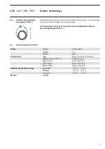
Temperature input
– Temperature sensor TS/K 1.1
For recording the ambient
temperature
–
Potentiometer
4.7
k
액
, +/– 10 % linear
as a setpoint temperature controller
for a setpoint adjustment of +/– 3 °C
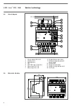
Operating and display elements
– Red LED
For entering the physical address
and for testing the output
functions
– Programming button
For entering the physical
address
– Test button
For testing the heating, cooling
and fan outputs
2CDC 071 036 F0004

