3.4 Electrical connection
Electrical system
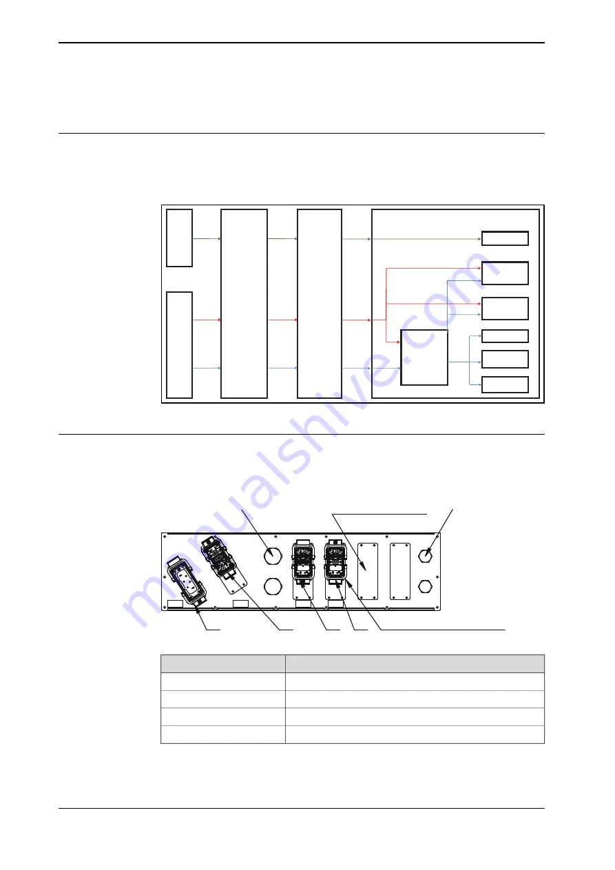
The electrical system of the Feather Duster V2 mainly exists in the process cabinet,
the ionization unit and the motor.
The Feather Duster V2 can be controlled by DeviceNet.
IRC5
Air
supply
Feather
Duster
Process
Cabinet
Slip ring
220V
DeviceNet
Compressed
Air
24V
DeviceNet
Compressed
Air
24V
DeviceNet
Compressed
Air
Feather Duster
Air curtain
DSQC651
BLDC
Motor
Ionizing Bar
Rotate Sensor
An!-collision
sensor
Air speed
sensor
5V AO
24V
24V
DO
DI/DO
xx1800000876
Process cabinet
There are five
Harting
connectors on the process cabinet.
For details, refer the circuit diagram (Art. No. 3HAX010000300) of the process
cabinet.
FD1
FD3
FD4
FD2
FD4
FD3
FD2
FD1
2xCover 32
2xCover 25
Cover:2x 3HAW050059700
Adaptor Plate: 3x3HAW050059705
xx1800001349
Function
Connector
Main power supply input
FD1
Signal
FD2
Compress air valve
FD3
Vacuum sensor
FD4
Continues on next page
72
Product manual - Feather Duster V2
3HAX010000210 Revision: A
© Copyright 2018 ABB. All rights reserved.
3 Installation and commissioning
3.4 Electrical connection
Summary of Contents for Feather Duster V2
Page 1: ...ROBOTICS Product manual Feather Duster V2 ...
Page 12: ...This page is intentionally left blank ...
Page 168: ...This page is intentionally left blank ...
Page 172: ...This page is intentionally left blank ...
Page 180: ...This page is intentionally left blank ...
Page 188: ...This page is intentionally left blank ...
Page 190: ......
Page 191: ......


