4 Installation and commissioning
4.2.3. Instructions for the installation of the steel structure frame
3HAW050027150 Revision: C
48
©
Co
py
rig
h
t 201
3-
101
6 ABB. All righ
ts reser
v
ed.
7.
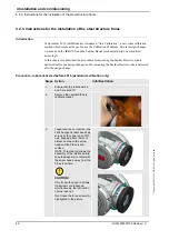
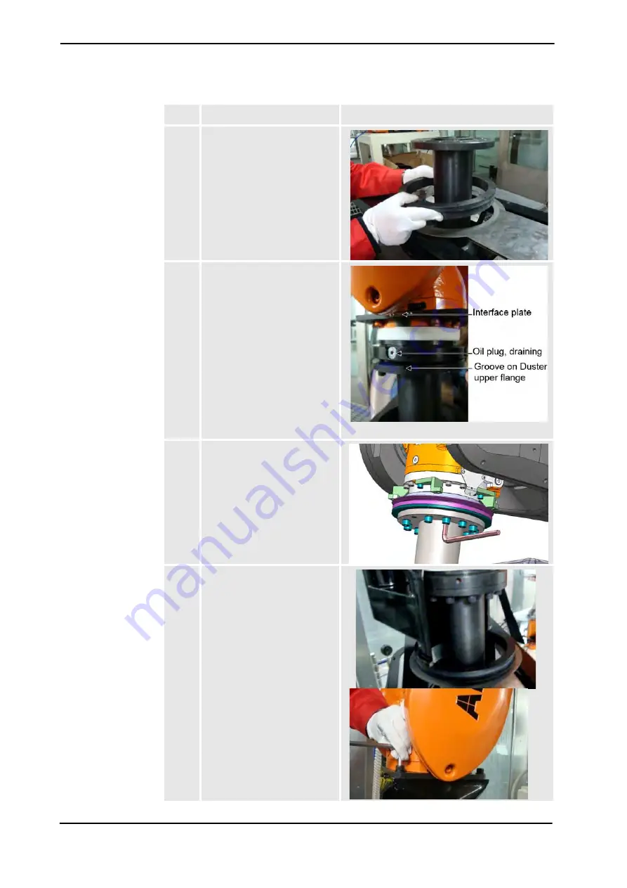
Set the sealing guide and the
sealing rubber ring on the steel
plate.
8.
Jog the robot vertically and bring
its roleface down in contact with
the steel structure frame.
Pay attention to the orientation
of installation: there is a 3mm
deep groove on the top of the
Feather Duster steel column
which must be aligned with the
0°calibration mark of the robot
6th axis.
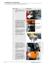
Pre-tighten 2x M12x35 hexagon
socket head cap screws. Insert
the Ø12mmx28 dowel pin to
locate the steel frame.
9.
Tighten all 11 hexagon socket
head cap screws M12x35.
10.
Assemble one half of the
exhaust hose connector (the
one with the connector) to the
interface plate. The other half
shouldn’t me assembled until all
mechanical installation is
complete.
Pay attention to the branch
orientation, make sure that the
calibration label is not hidden.
Tighten only the 2x upper
hexagon socket head M10
screws to the interface plate.
The 5 screws used to tighten the
cover to the sealing guide
should be tightened later, upon
the installation of the other
cover.
Steps Action
Info/IIIustration
Summary of Contents for Feather Duster
Page 1: ...Product manual Feather Duster ...
Page 2: ......
Page 12: ...3HAW050027150 Revision C 10 Copyright 2013 1016 ABB All rights reserved ...
Page 92: ... Copyright 2013 1016 ABB All rights reserved ...
Page 100: ... Copyright 2013 1016 ABB All rights reserved ...
Page 110: ......
Page 148: ... Copyright 2013 1016 ABB All rights reserved ...
Page 149: ......


