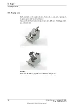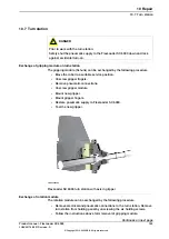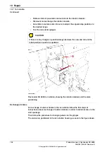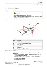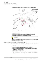
2 Remove the four bolts and nuts holding the bracket. See figure below.
xx1900000399
Figure 10.3: Grinding/deburring unit fastening system.
3 Pull the unit backwards.
4 Install the new unit.
5 Connect the pneumatic connection to the grinding/deburring unit.
6 Restore the pneumatic supply to FlexLoader SC 6000.
CAUTION
If there are any changes in position or design between the new and old unit the
robot positions must be updated.
Replacing the valves controlling the deburring/grinding units
One or more valve modules (Festo) can be replaced by the following procedure:
1 Disconnect the pneumatic connections that connects the valves to FlexLoader
SC 6000.
2 Disconnect the electrical connection to the distributor box.
3 Disconnect the pneumatic connections and the two M4 screws, placed
underneath, holding the valve.
4 Replace the valve with a new one.
5 Reinstall the air cleaning box in reverse order. Make sure the air cleaning
box is correctly connected to the pins placed in the FlexLoader SC 6000
frame.
Continues on next page
158
Product manual - FlexLoader SC 6000
3HAC051768-001 Revision: D
© Copyright 2014-2020 ABB. All rights reserved.
10 Repair
10.9 Grinding/Deburring units (option)
Continued
Summary of Contents for FlexLoader SC 6000
Page 1: ...ROBOTICS Product manual FlexLoader SC 6000 ...
Page 8: ...This page is intentionally left blank ...
Page 12: ...This page is intentionally left blank ...
Page 78: ...This page is intentionally left blank ...
Page 172: ...This page is intentionally left blank ...
Page 174: ...This page is intentionally left blank ...
Page 176: ...This page is intentionally left blank ...
Page 178: ...This page is intentionally left blank ...
Page 182: ...This page is intentionally left blank ...
Page 184: ...This page is intentionally left blank ...
Page 186: ...This page is intentionally left blank ...
Page 192: ...This page is intentionally left blank ...
Page 224: ...This page is intentionally left blank ...
Page 283: ......


