Note
Note that the calibration plate must not move during the calibration. If it moves,
you must start over with the calibration.
Note
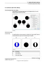
It is possible to reduce the area that is used for calibration. This can be useful
in several cases, e.g. when the field of view is large and there are visible objects
outside of the calibration plate.
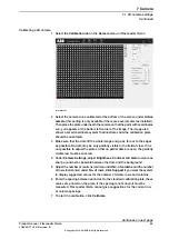
Select the define position tool and draw a red rectangle around the valid
calibration dots. Then perform the calibration as described above.
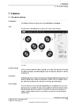
Settings
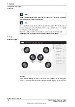
General Settings
xx1800000248
Under
General Settings
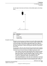
, enter the correct camera height to ensure that the system
sends the correct coordinates to the robot. The camera height is measured in mm
Continues on next page
100
Product manual - FlexLoader Vision
3HAC051771-001 Revision: B
© Copyright 2014-2018 ABB. All rights reserved.
7 Camera
7.1 2D camera settings
Continued
Summary of Contents for FlexLoader Vision
Page 1: ...ROBOTICS Product manual FlexLoader Vision ...
Page 8: ...This page is intentionally left blank ...
Page 12: ...This page is intentionally left blank ...
Page 14: ...This page is intentionally left blank ...
Page 16: ...This page is intentionally left blank ...
Page 62: ...This page is intentionally left blank ...
Page 96: ...This page is intentionally left blank ...
Page 180: ...This page is intentionally left blank ...
Page 218: ...This page is intentionally left blank ...
Page 286: ......
Page 287: ......


