7.2 3D camera settings
Introduction
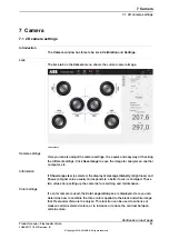
The
Camera
window for 3D camera has the same three tabs as for 2D cameras,
but the settings differ.
Live
For 3D cameras, the
Live
tab is only used to save images (as the 3D camera does
not need settings for brightness, contrast and gain). Therefore only the
Save image
button is visible.
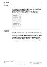
Calibration
In order for FlexLoader Vision to send the correct coordinates to the robot, the
system must be calibrated together, i.e. the coordinate systems of FlexLoader
Vision and the robot must be made to correspond. For this purpose, the supplied
calibration plate and calibration tool are used.
The following sections describes how to calibrate FlexLoader Vision. For information
about how to calibrate the robot, see the separate robot product manual.
Start by calibrating the coordinate system
wCamera1
(or for example
wCamera2
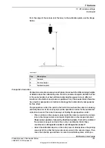
for camera 2) in the robot. The coordinate system should lie with the x-axis along
the long side of the pallet, the y-axis along the short side of the pallet, and the
z-axis pointing upwards (for example, it can lie on the guides for the pallets).
Fit the calibration cone on the robot and ensure that the tool center point (TCP)
for it is used in all calibration positions. If the calibration positions do not exist they
must be created to facilitate the calibration. For more information on this, see
Calibrating for use with a 3D camera on page 188
All positions should lie in
wCamera1
(the 3D camera is camera 1) and be within
the robot’s range and the camera’s measurement range. The calibration cone
should point directly upwards at each point. If the camera is inclined in relation to
wCamera1
, inclined cone positions should be considered.
FlexLoader Vision needs 9 to 30 calibration points (typically 15) in order to perform
calibration calculations. Prepare the RAPID module
Calibration3D.sys
with all
robot positions used during calibration (see routine
Calibration3DUpdatePositions
).
It is strongly recommended to use 5 points as far down as possible, one in each
corner of the area where the pallets will stand and 1 in the middle. Then a further
5 positions located in the same way at a medium height and, finally, a further 5
located in the same way at a height close to the maximum height. Remember that
the positions must always be within the measurement volume of the camera.
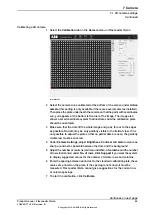
In FlexLoader Vision, select
Camera
and the tab
Calibration
. Enter cone diameter
and cone angle of the robot’s calibration cone. Click
Calibrate
.
After a confirmation prompt, FlexLoader Vision will reset the current calibration.
This means that the displayed part of the camera field of view may have moved
considerably.
Continues on next page
Product manual - FlexLoader Vision
103
3HAC051771-001 Revision: B
© Copyright 2014-2018 ABB. All rights reserved.
7 Camera
7.2 3D camera settings
Summary of Contents for FlexLoader Vision
Page 1: ...ROBOTICS Product manual FlexLoader Vision ...
Page 8: ...This page is intentionally left blank ...
Page 12: ...This page is intentionally left blank ...
Page 14: ...This page is intentionally left blank ...
Page 16: ...This page is intentionally left blank ...
Page 62: ...This page is intentionally left blank ...
Page 96: ...This page is intentionally left blank ...
Page 180: ...This page is intentionally left blank ...
Page 218: ...This page is intentionally left blank ...
Page 286: ......
Page 287: ......


