Note/Illustration
Action
Linearly position the other preassembled section
beside the section above.
3
xx1800001882
Connect the preassembled sections with screws
not mounted.
4
xx1800001883
Level the track module with the M60 screws. See
Geometric alignment of FlexTrack IRT 501 on
page 76
.
Note
Ensure the geometric alignment of the FlexTrack
with an optical level or a laser tracker. Note that,
at this stage, you can only check the horizontal
alignment based on the sidemember upper sur-
face. The final alignment will be given by the
measurements done based on the linear guide-
ways position.
5
Adjust the leveling screws until all leveling screws
touch the ground.
6
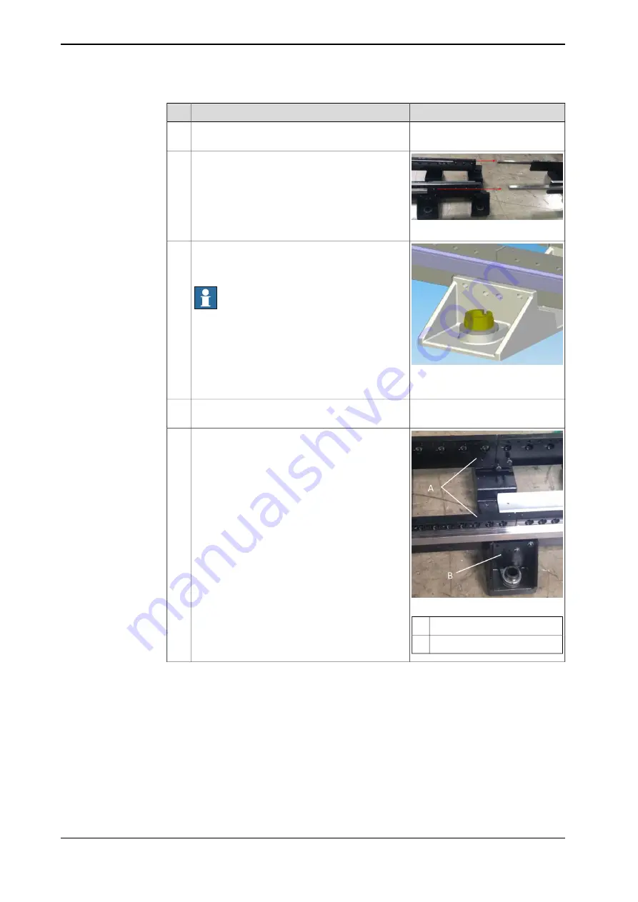
xx1800001884
Sidemember
A
Crossmember
B
Slightly tighten screws connecting the sidemem-
ber and the crossmember.
7
Continues on next page
66
Product manual - FlexTrack IRT501-66/66R/90/90R
3HAW050008590-001 Revision: C
© Copyright 20042018 ABB. All rights reserved.
2 Installation and commissioning
2.5.1 Procedure of assembly
Continued
Summary of Contents for FlexTrack IRT501 Series
Page 1: ...ROBOTICS Product manual FlexTrack IRT501 66 66R 90 90R ...
Page 8: ...This page is intentionally left blank ...
Page 38: ...This page is intentionally left blank ...
Page 118: ...This page is intentionally left blank ...
Page 174: ...This page is intentionally left blank ...
Page 178: ...This page is intentionally left blank ...
Page 182: ...This page is intentionally left blank ...
Page 186: ...This page is intentionally left blank ...
Page 198: ...This page is intentionally left blank ...
Page 200: ...This page is intentionally left blank ...
Page 202: ......
Page 203: ......


